| Picture | Description |
|---|---|
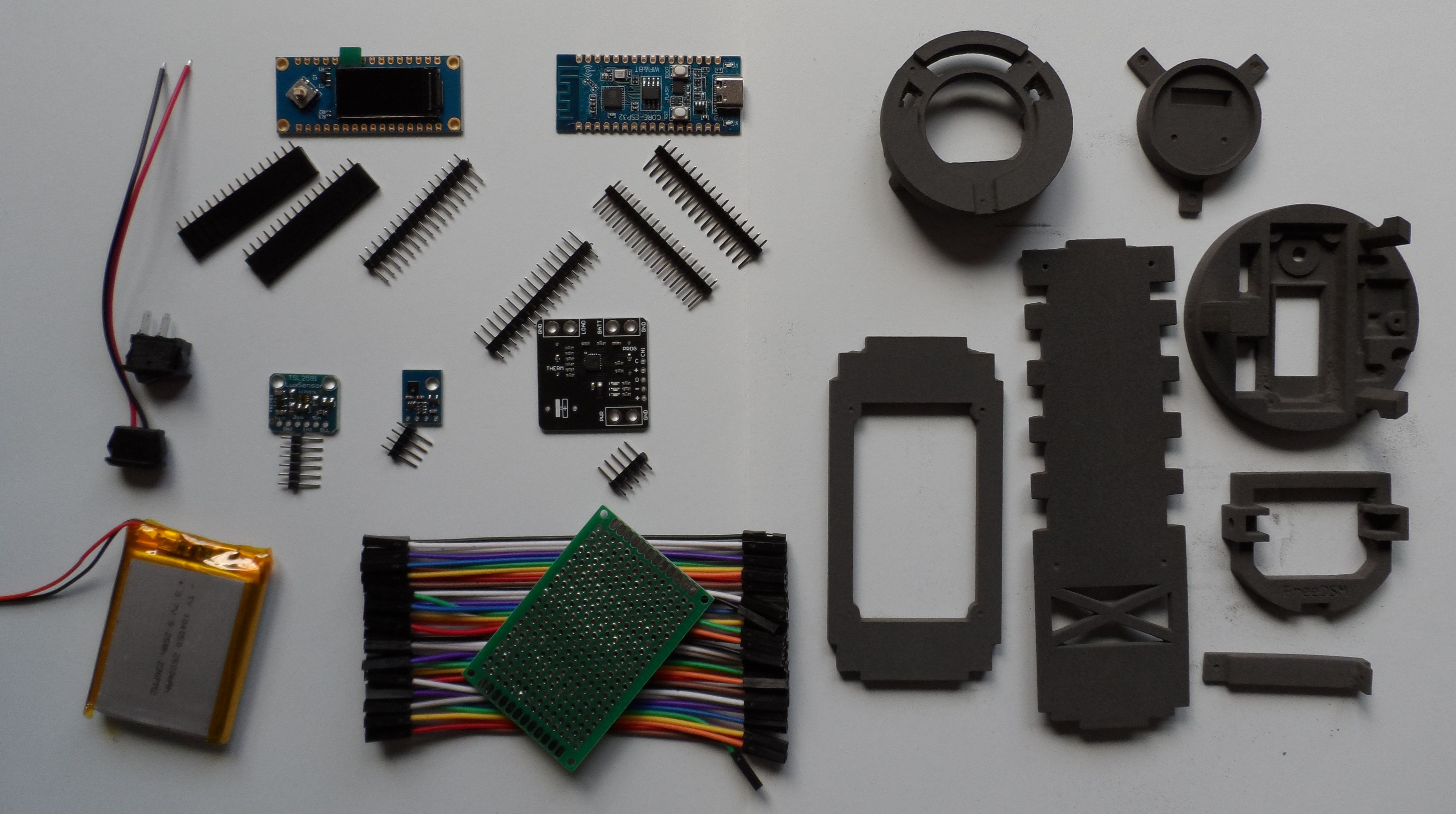 |
Main components. Additionally, 2 100 Ohm resistors and pin header not in the picture |
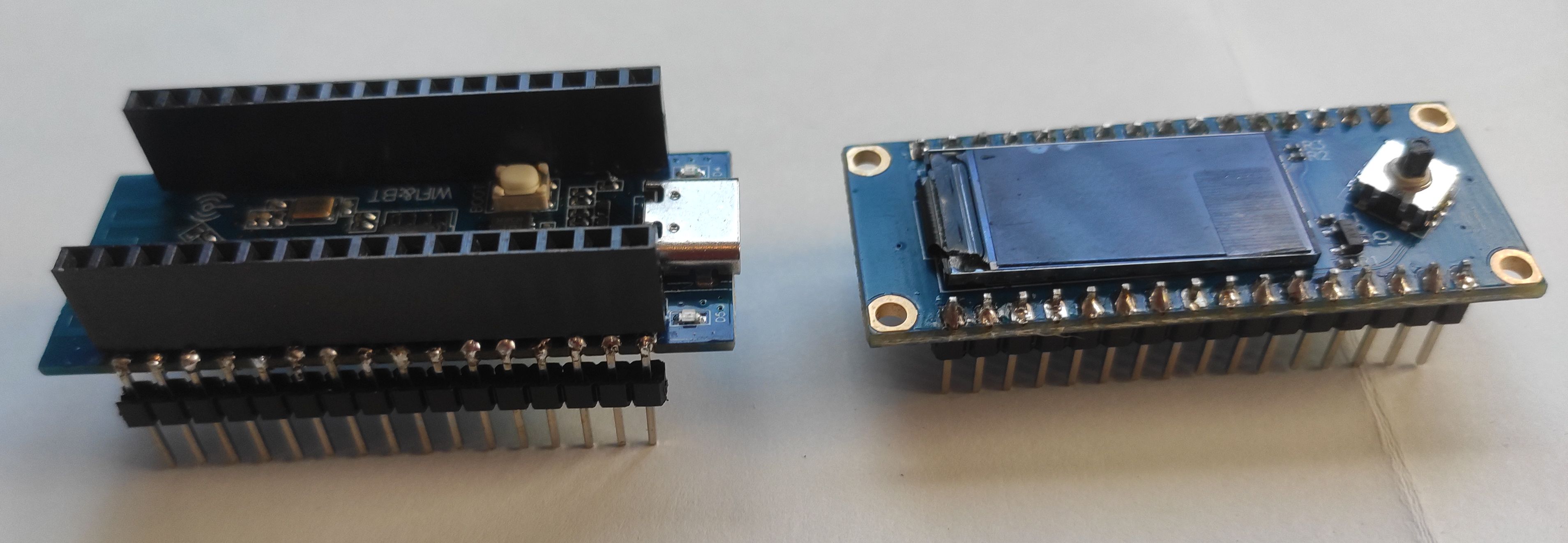 |
Pin soldering ESP32 C3 CORE and Air 101 display |
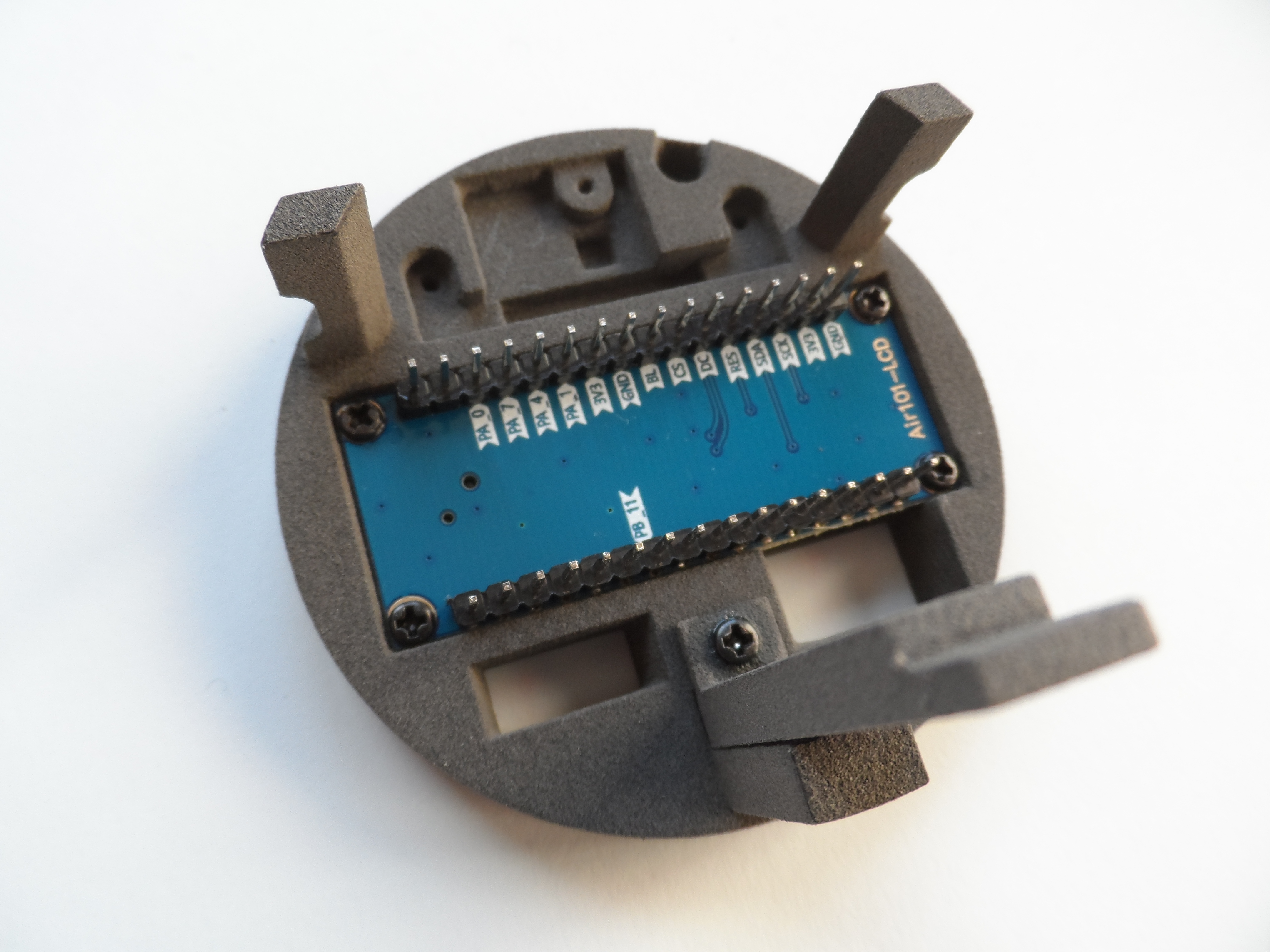 |
Screw the display to the round part |
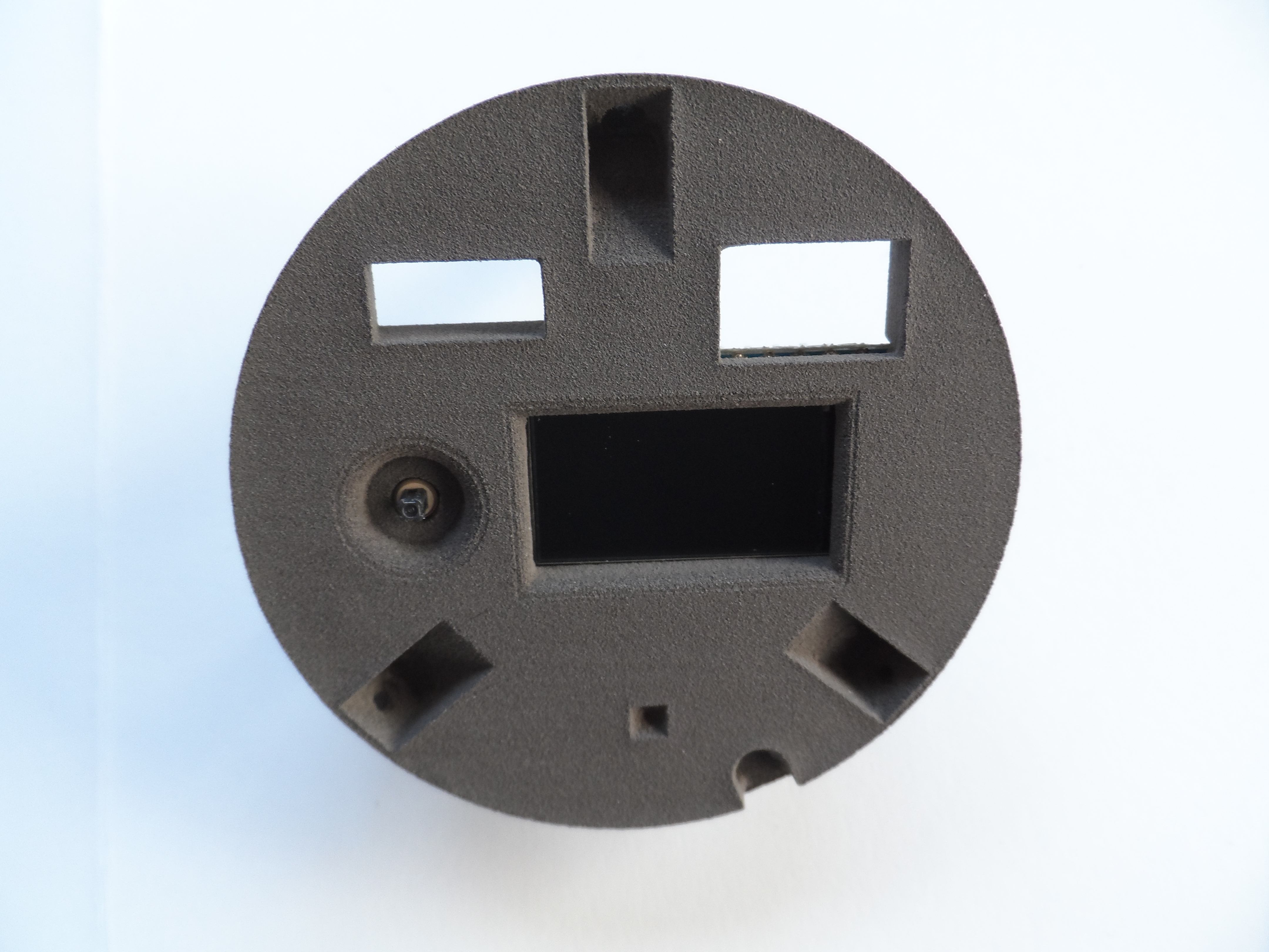 |
This is how it looks from the outside |
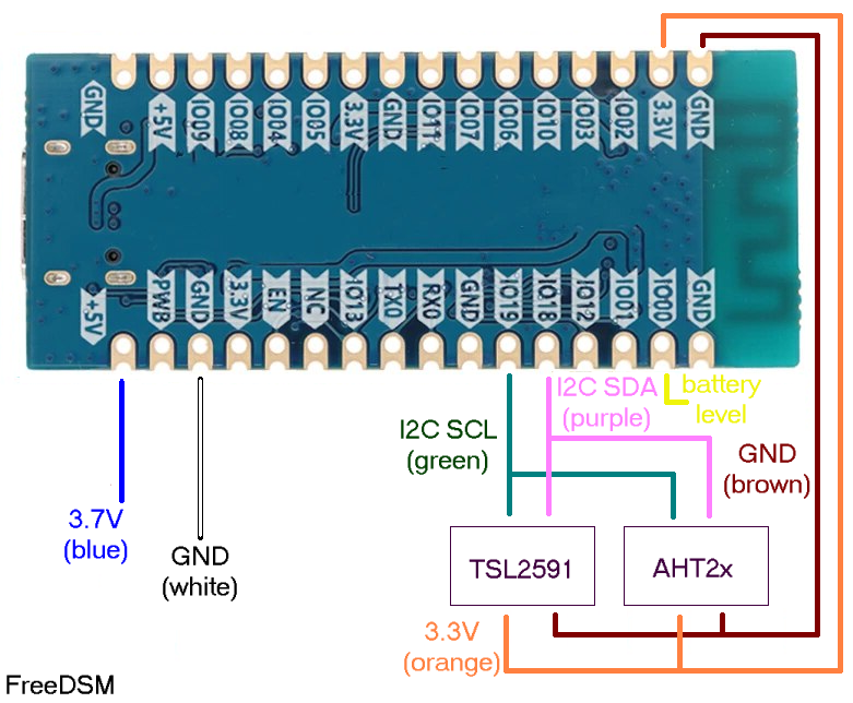 |
Wiring scheme |
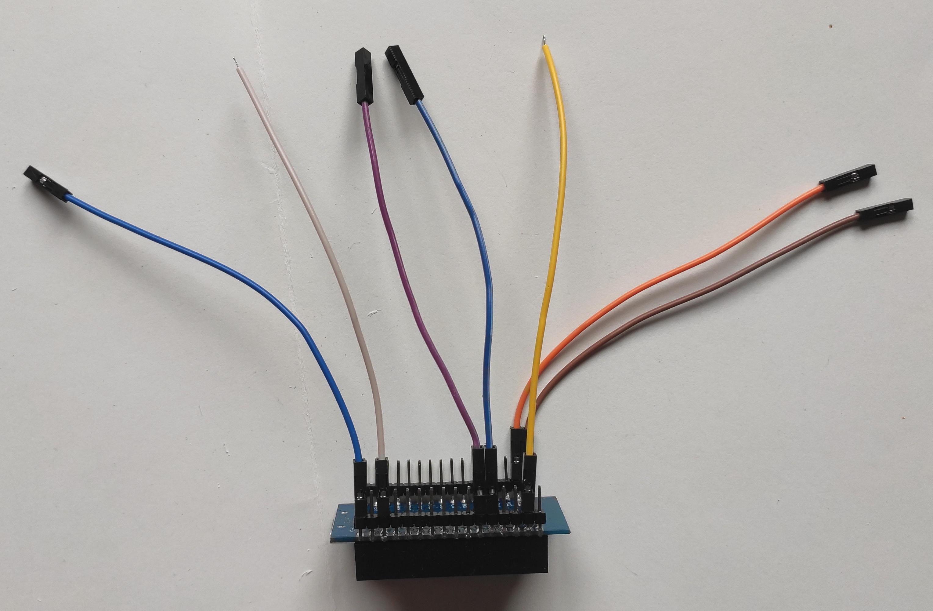 |
Wires connected to the ESP32 |
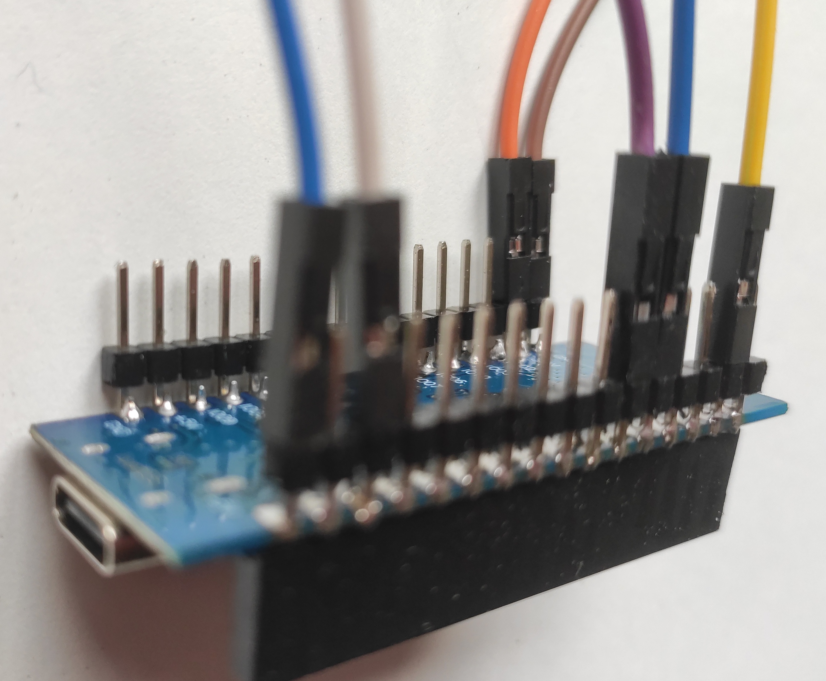 |
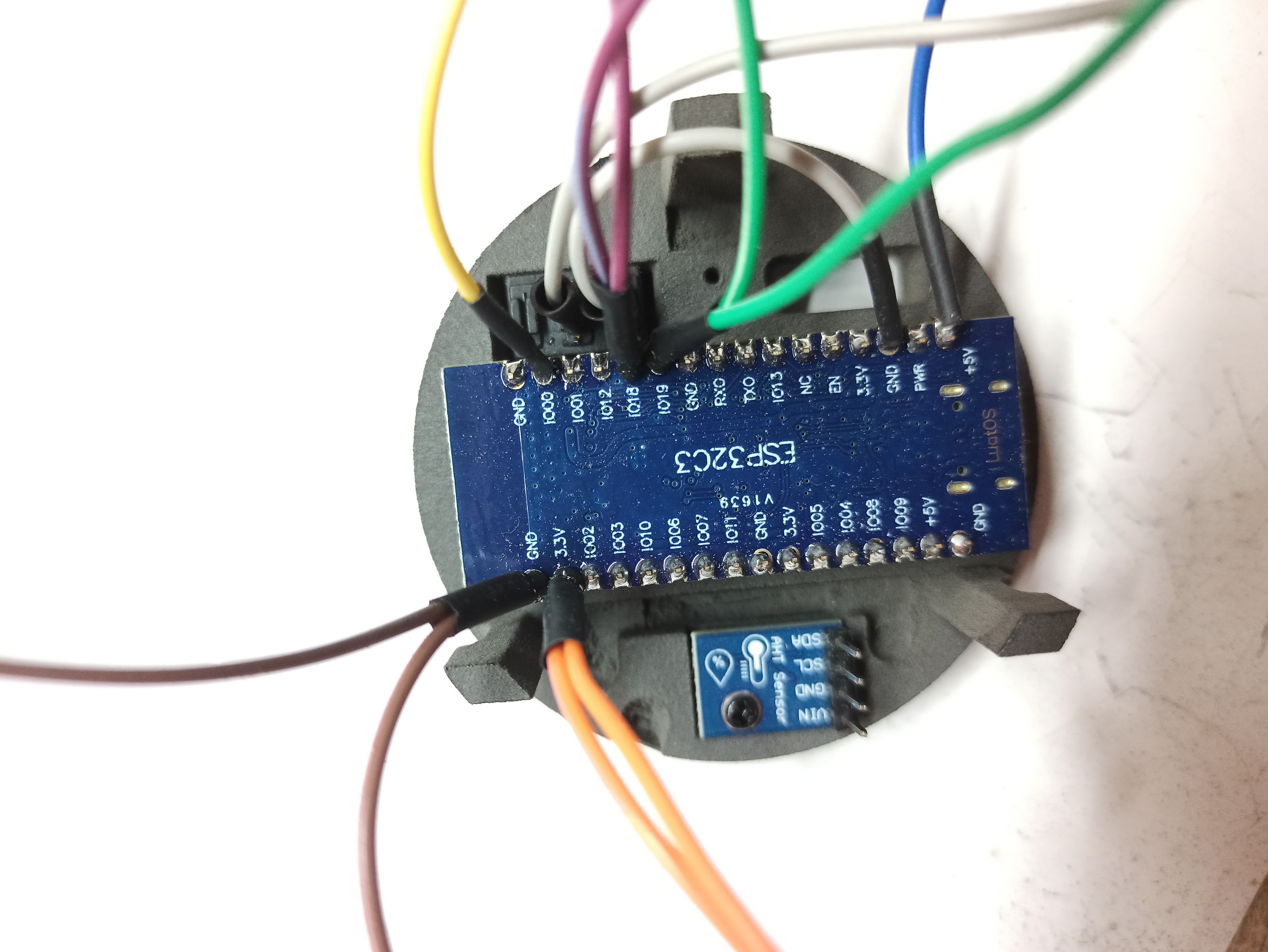
A more detailed picture of the connections to the ESP32 |
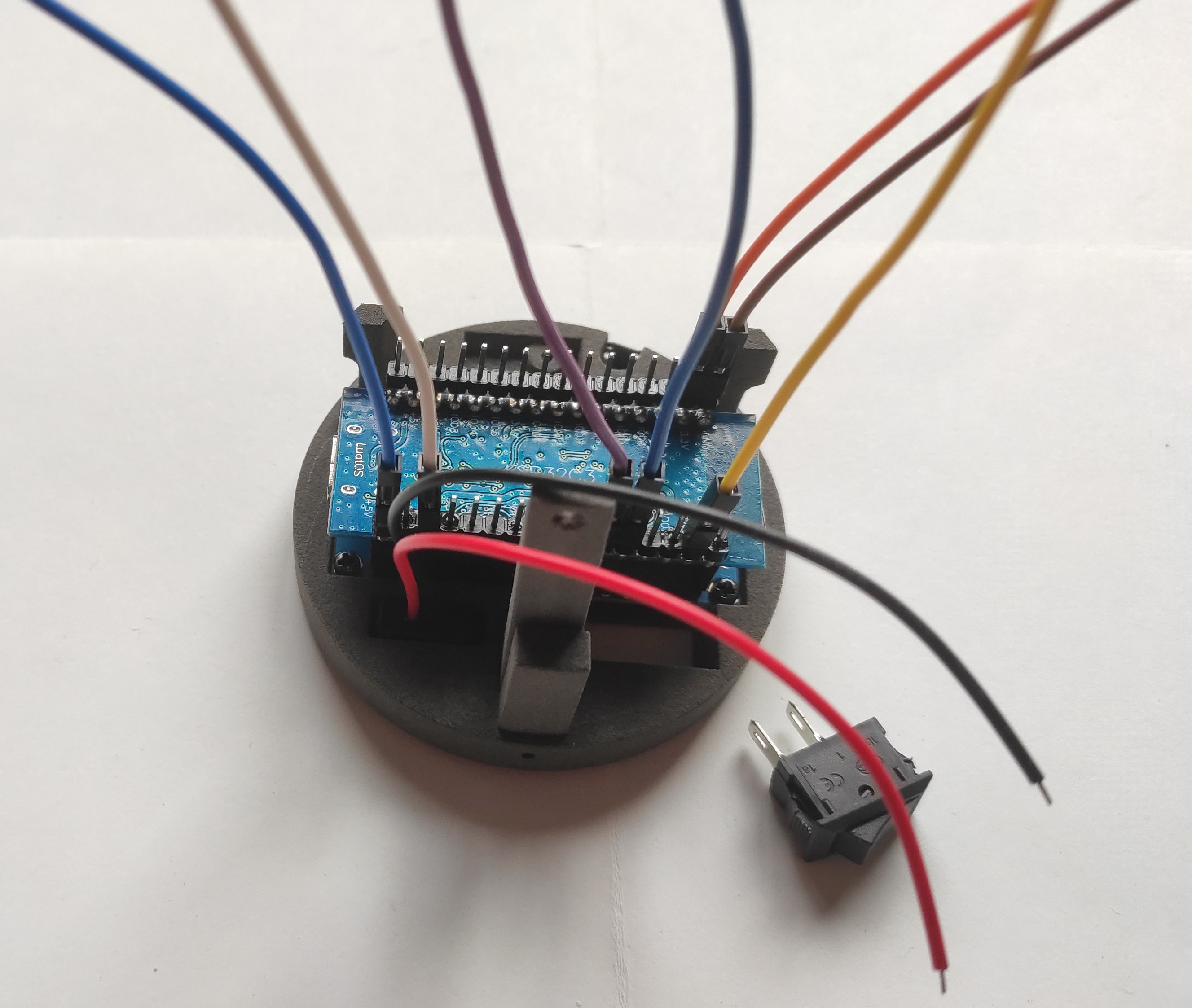 |
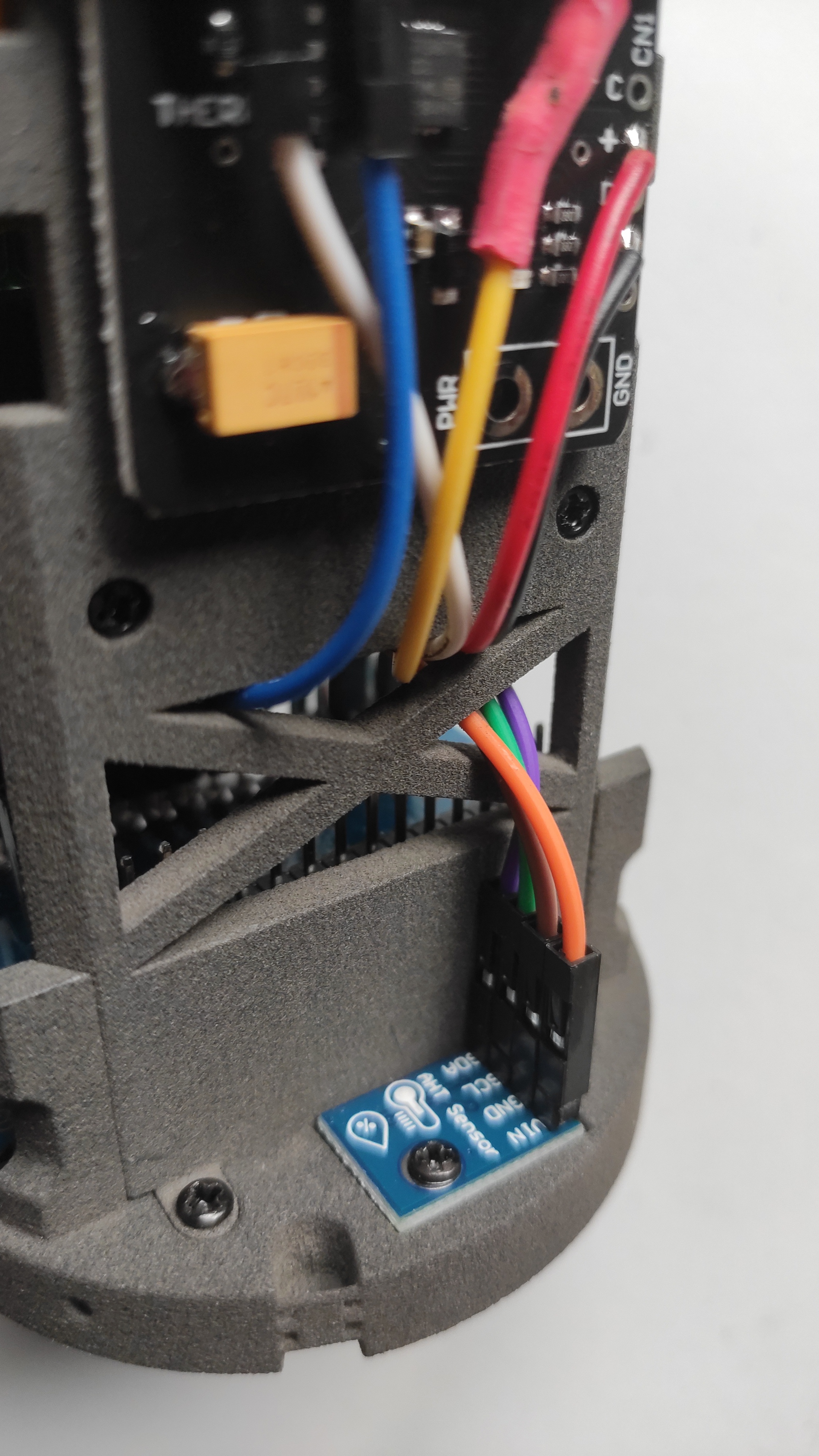
ESP32 mounted on the round part. Red and black wire from the USB-C go to the MCP battery controller. Blue wire from the ESP32-C3 board also goes to the MCP battery controller. The white wire in the picture and the one, also white, from the MCP battery controller must be connected later to the switch. |
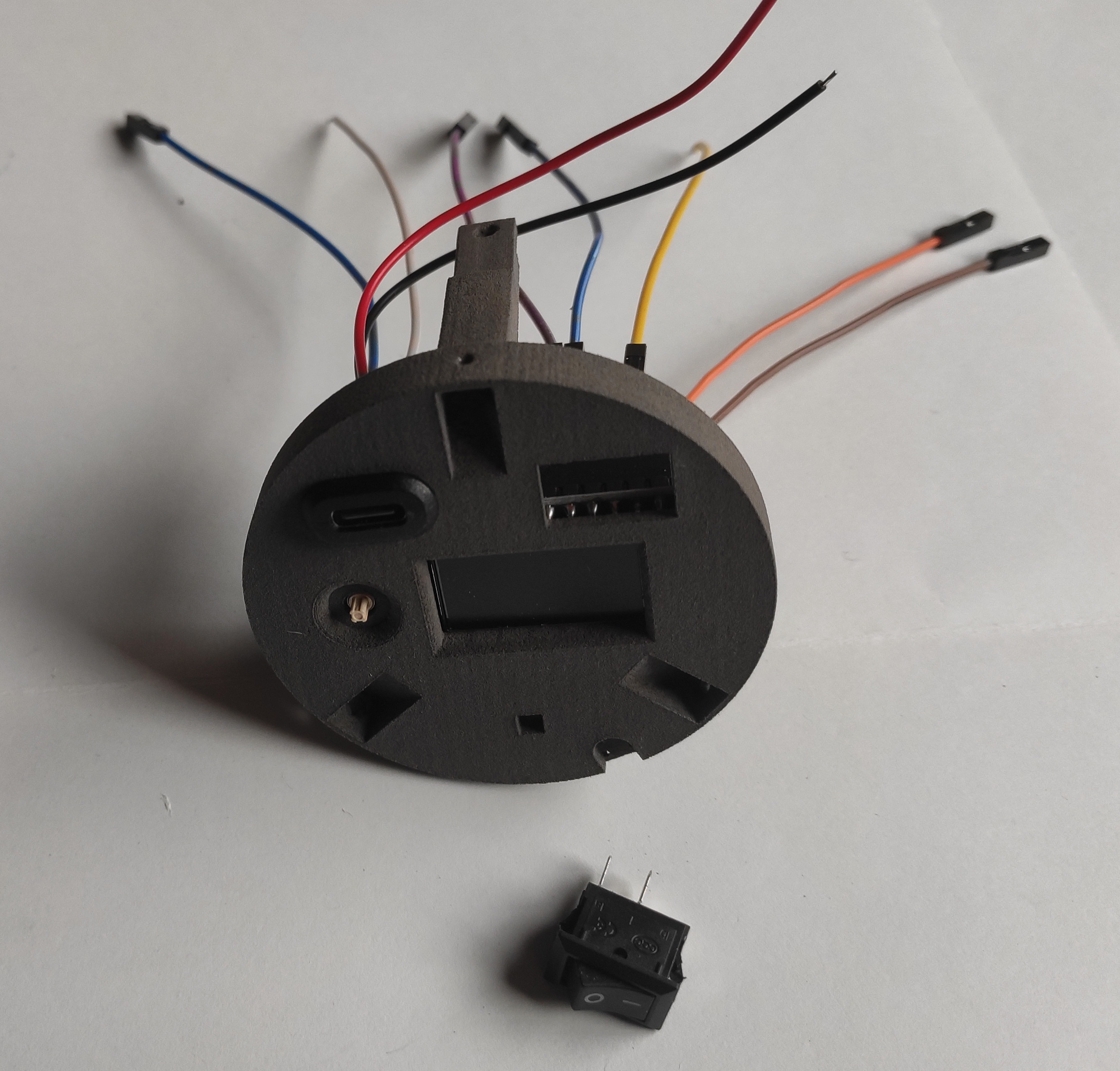 |
Front of the round part with display and USB-C, wired in the back |
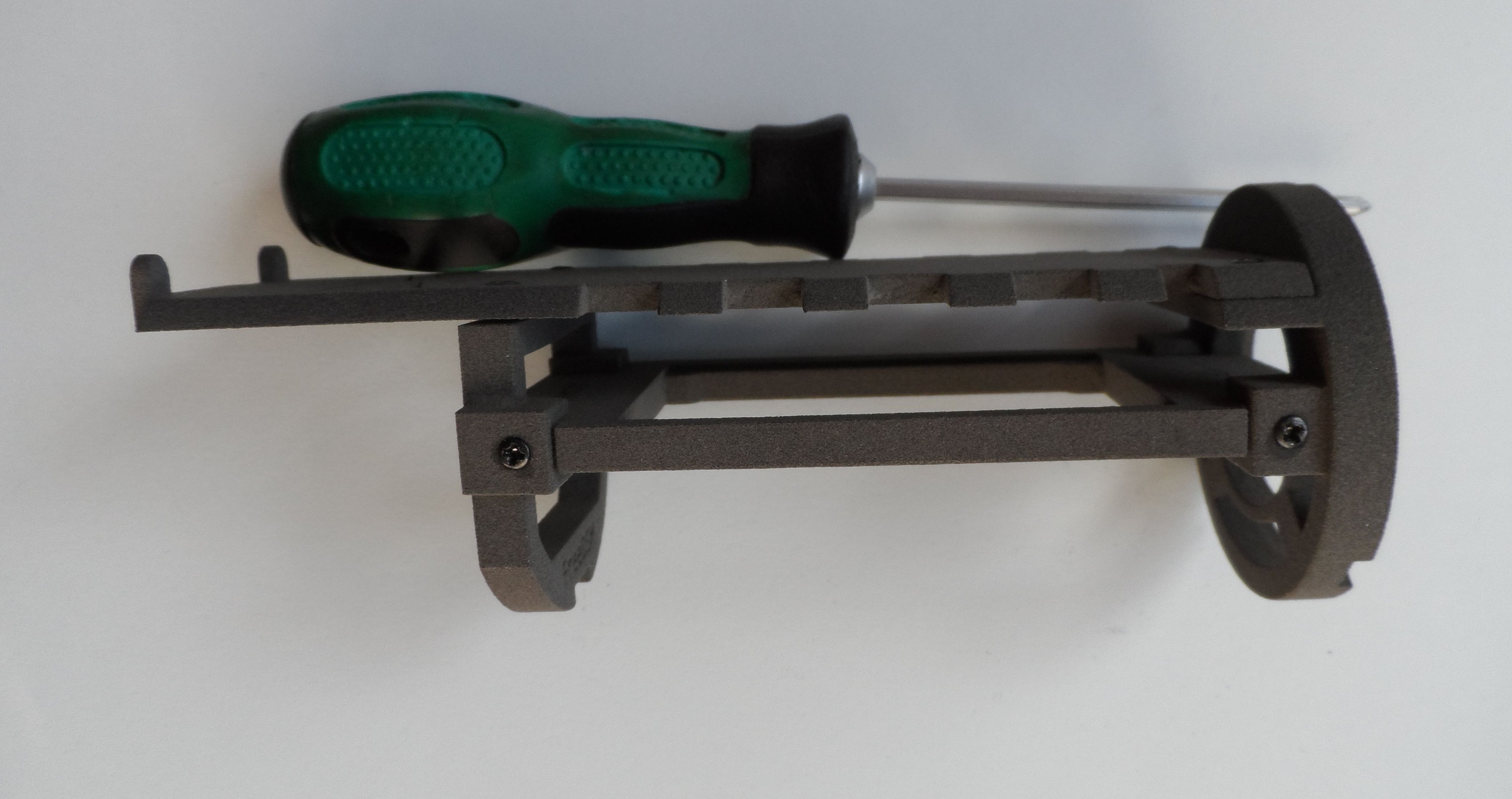 |
Chassis mounted, except TSL2591 top support and round front (display) |
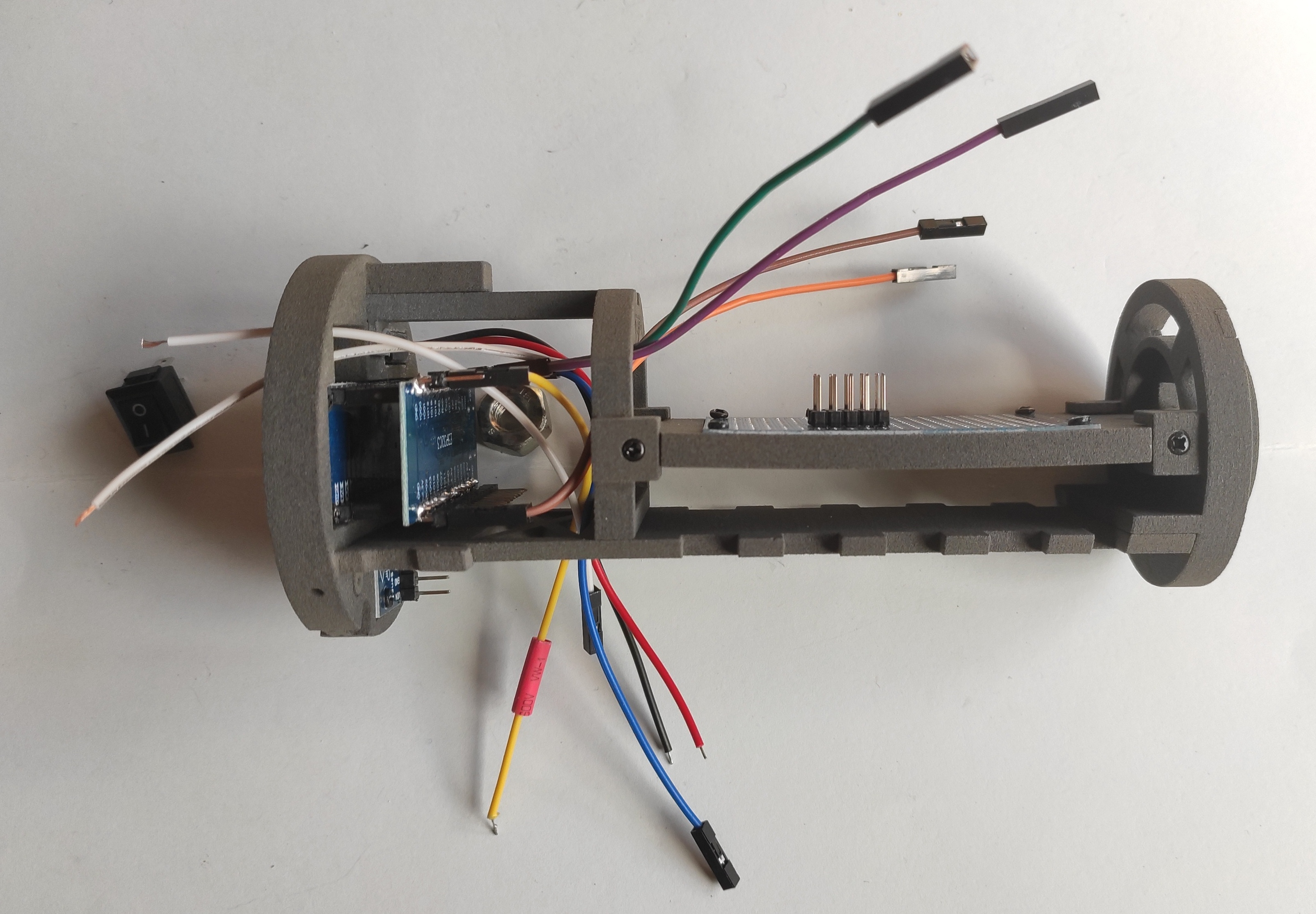 |
Complete chassis with wires |
 |
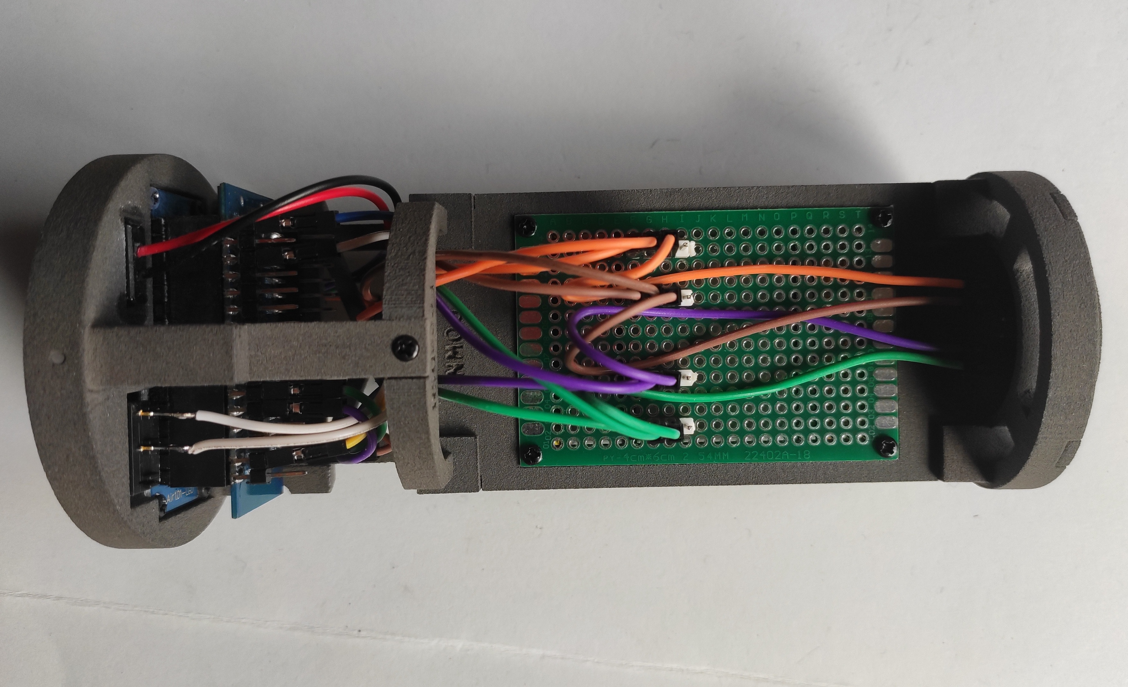
Complete chassis with wires (PCB side) |
 |
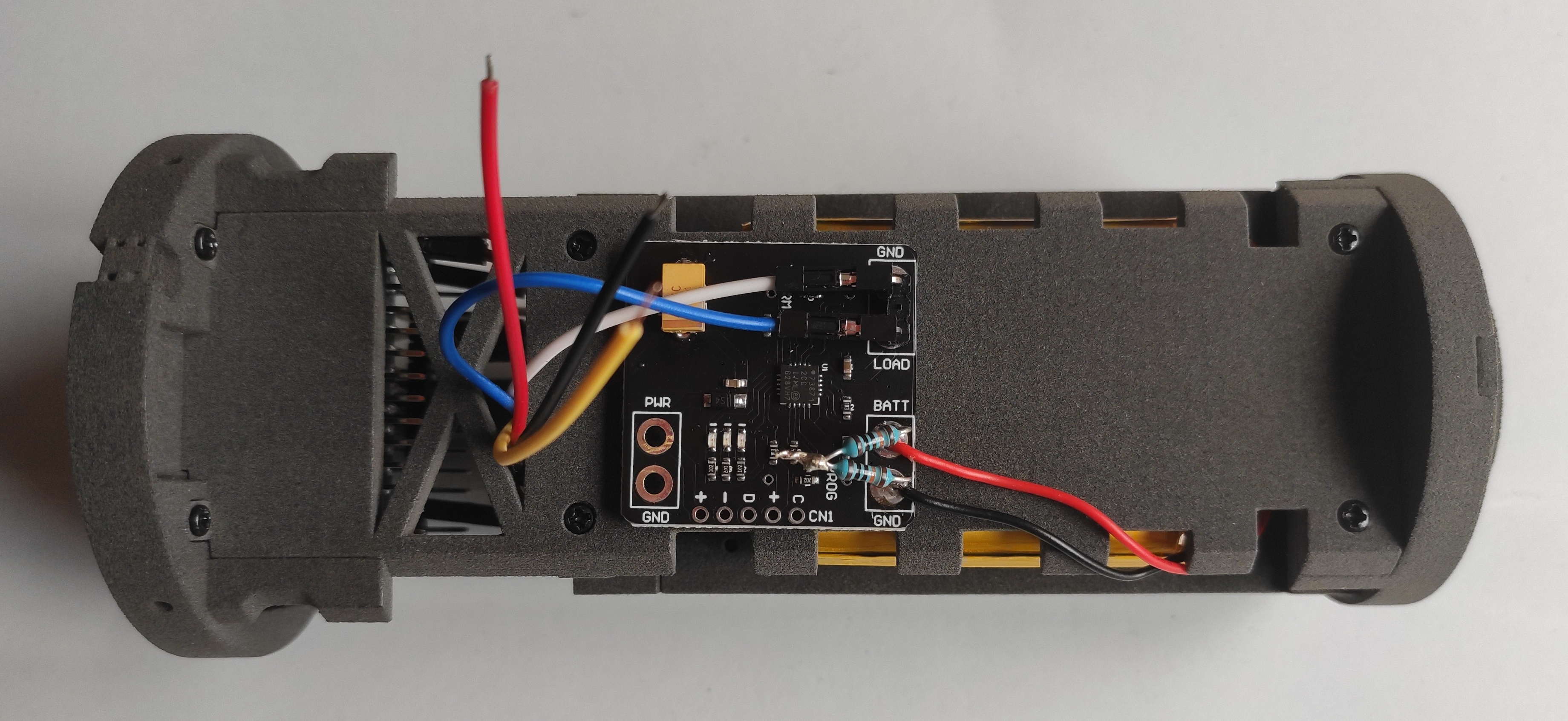
Complete chassis with wires (charge regulator side) |
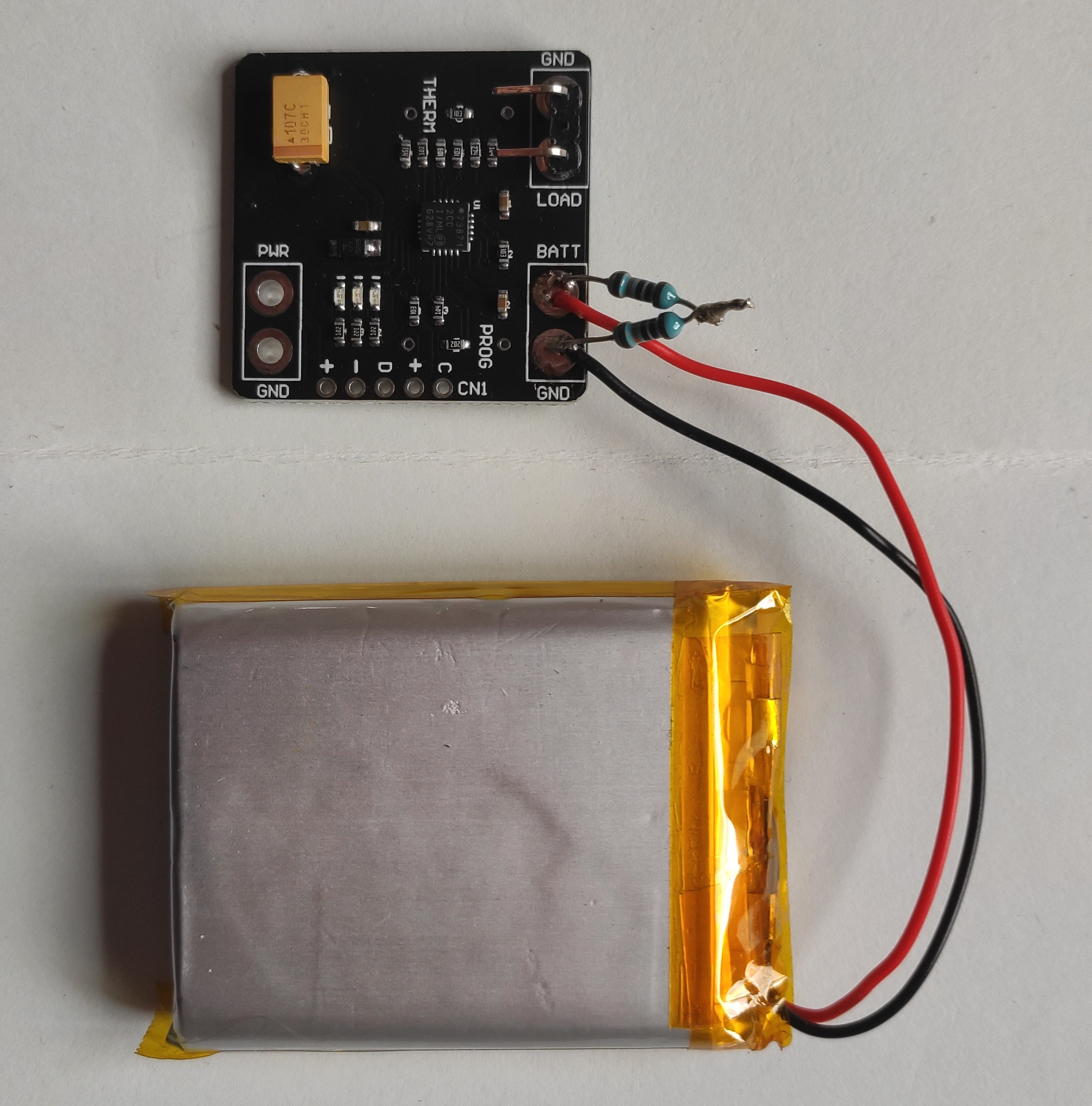 |
MCP battery charge controller |
 |
MCP connections detail |
 |
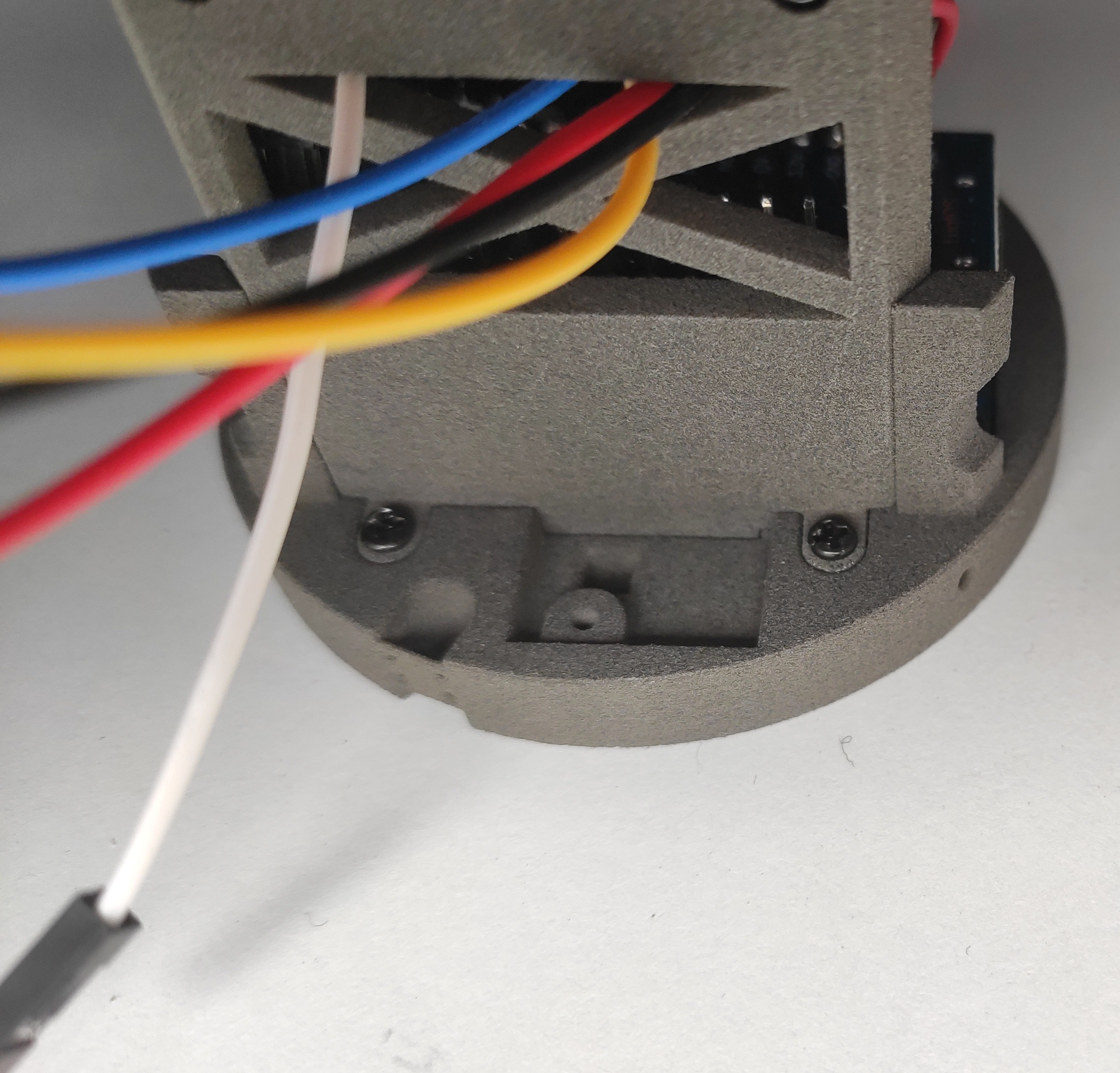
Stick battery and regulator with double side tape and connect the Dupont connectors LOAD(blue) and GND (white) |
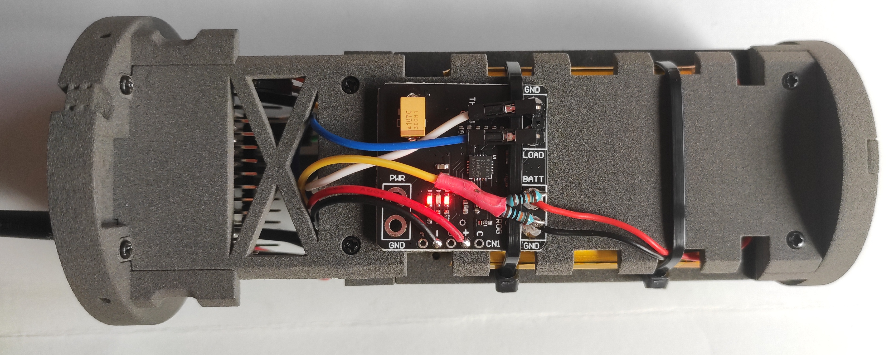 |
Solder USB-C wires and yellow wire for battery monitoring (protected with tape) |
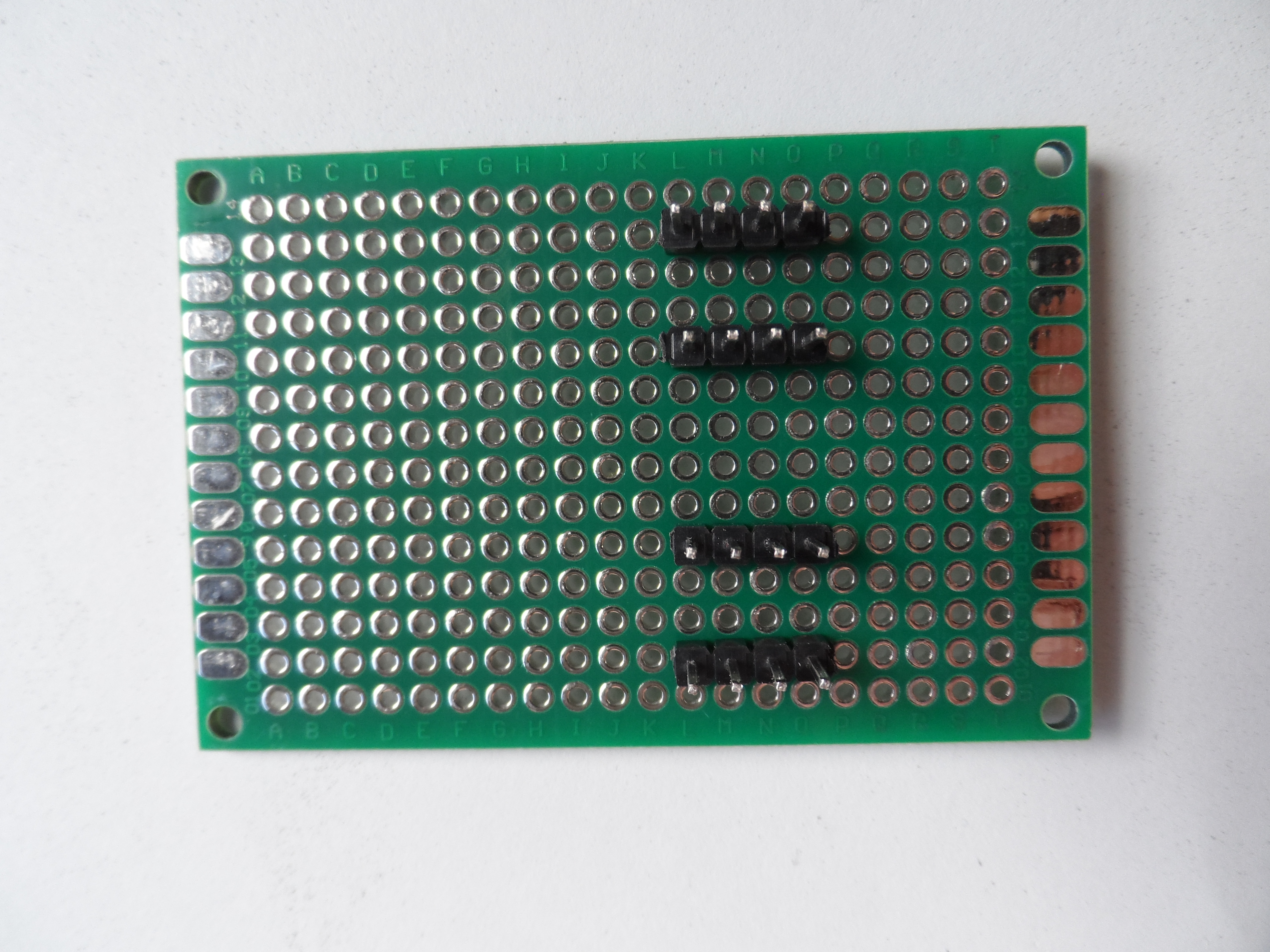 |
Prepare the PCB with 4 blocks of 4 pins. Here is the PCB front, with connections for 3.3V / GND / SCL / SDA |
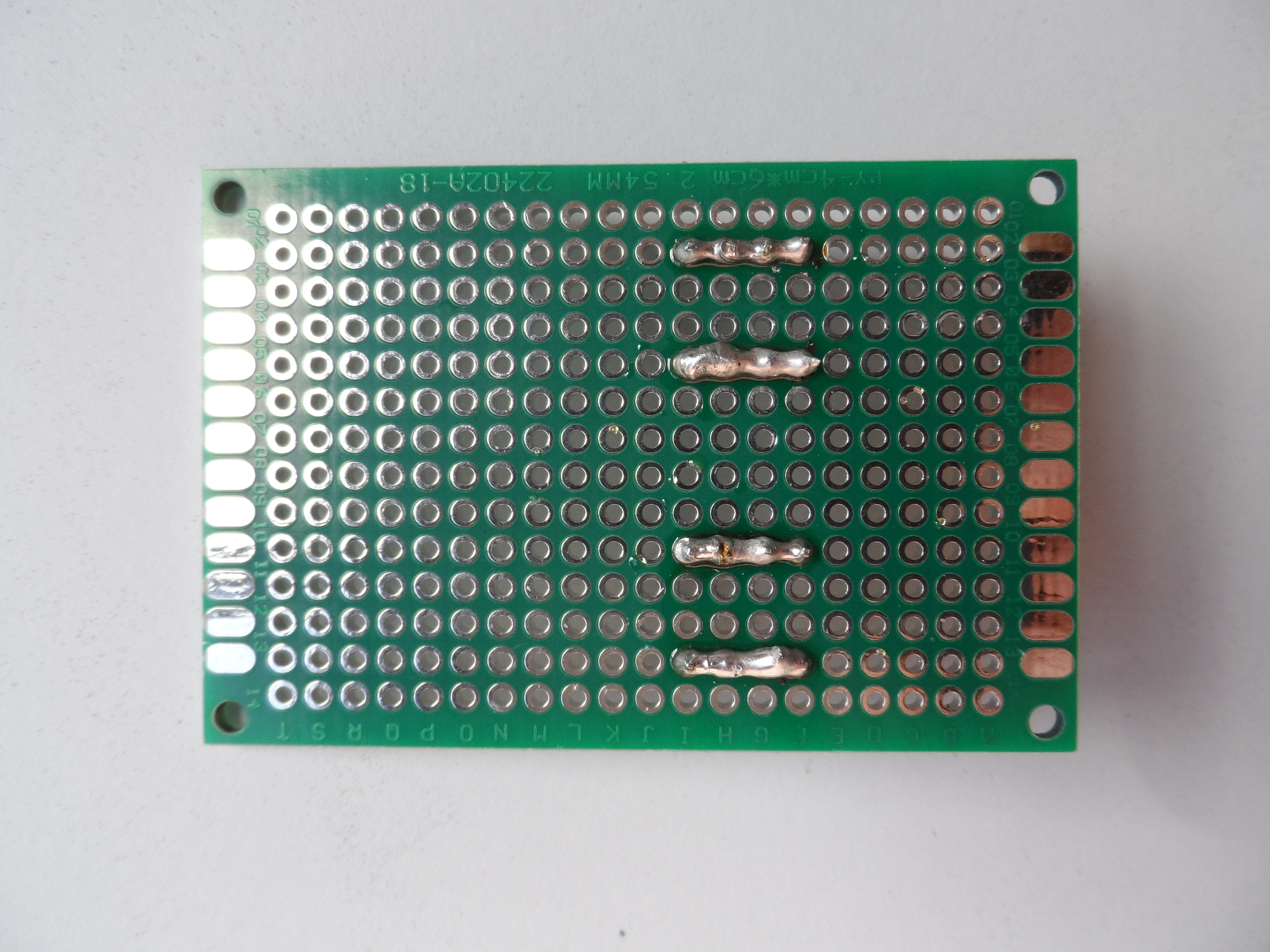 |
PCB back, joined pins of each block |
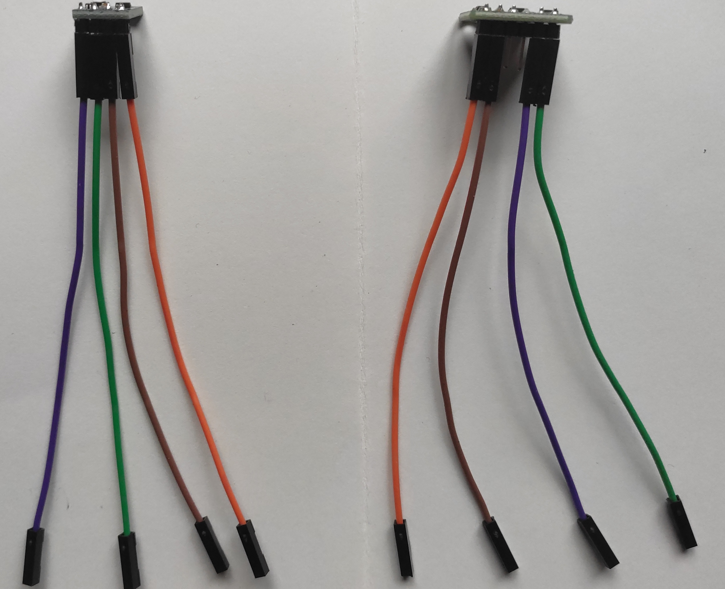 |
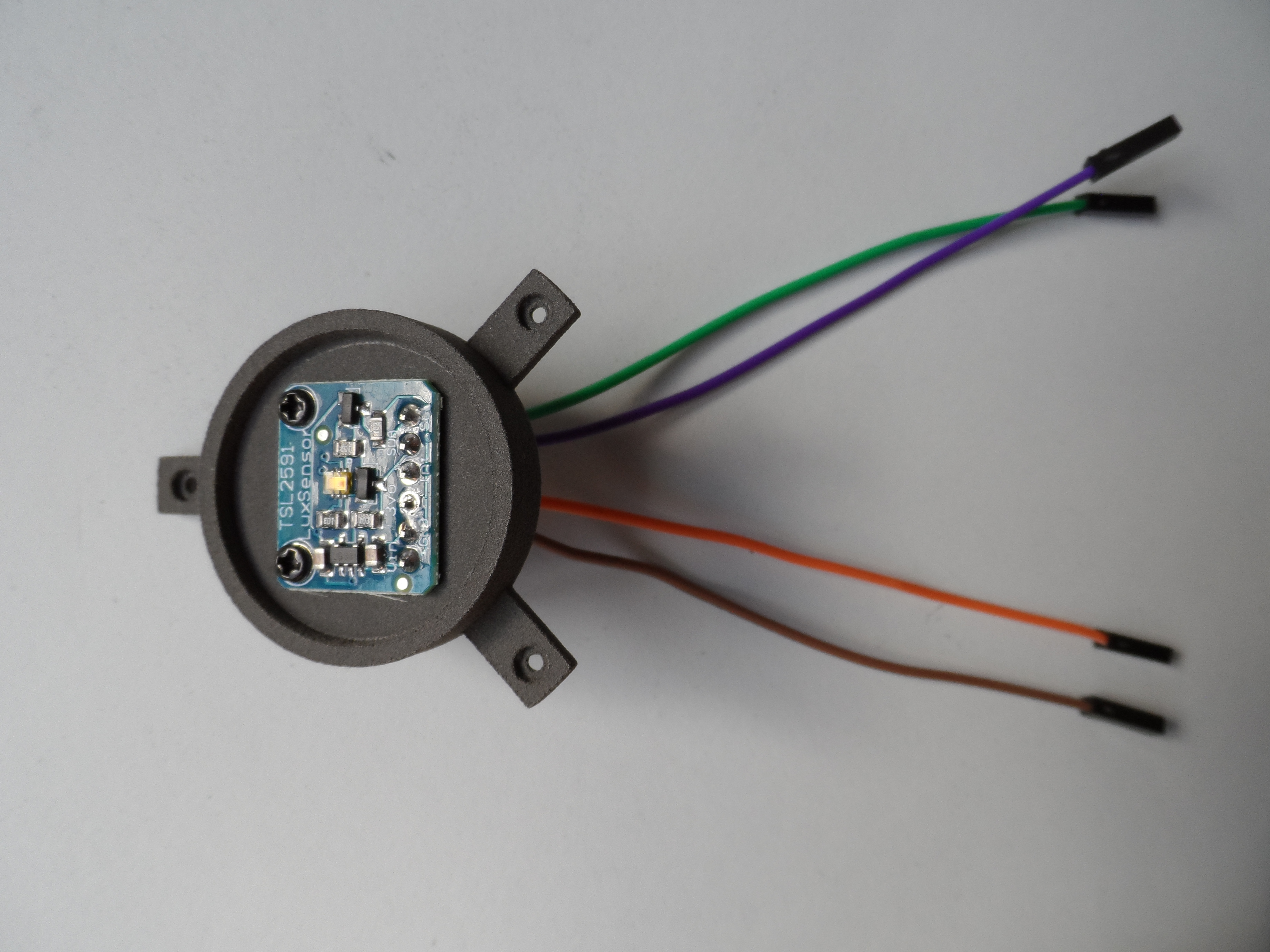
TSL2591 and AHT21 with wires |
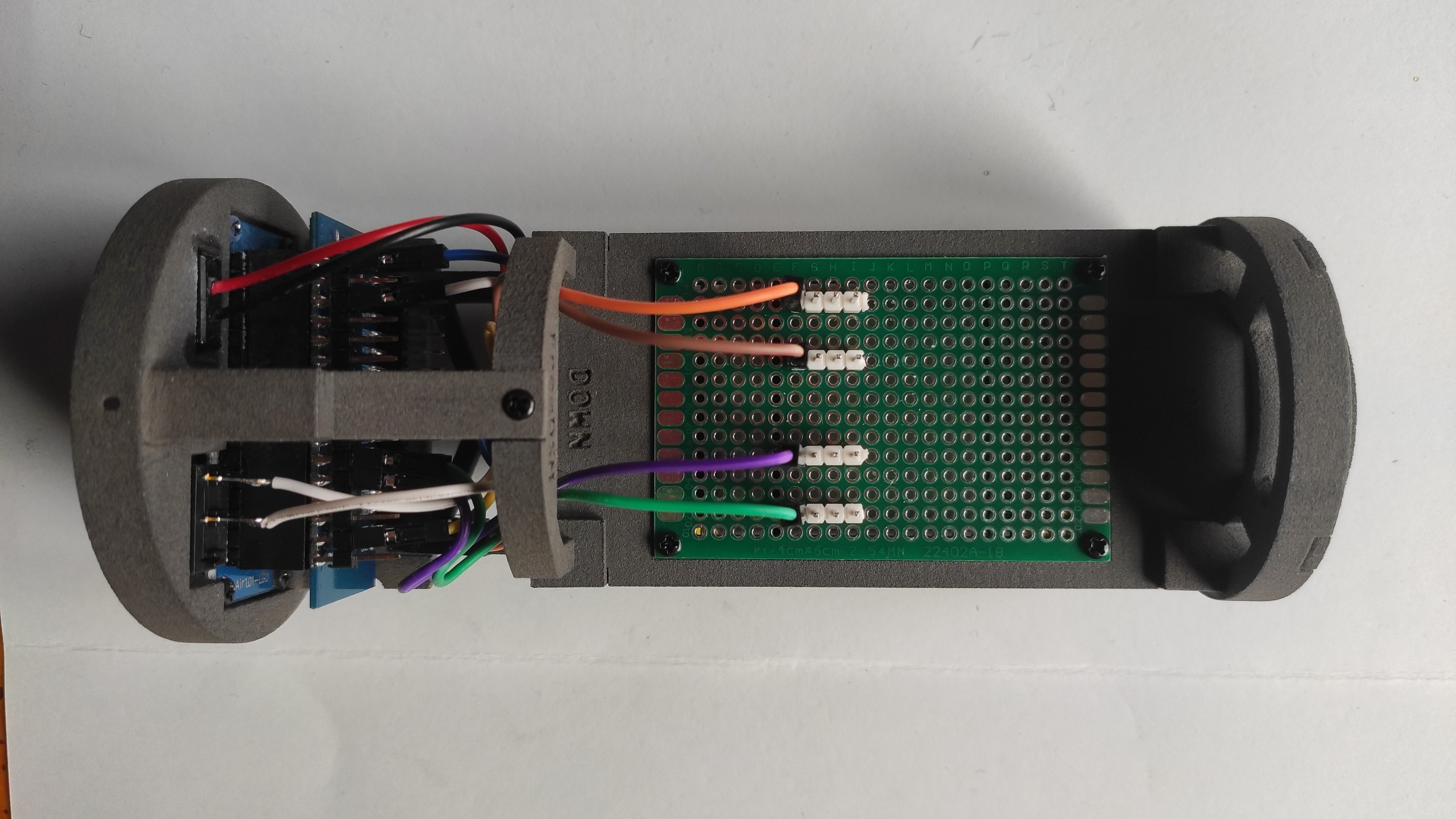 |
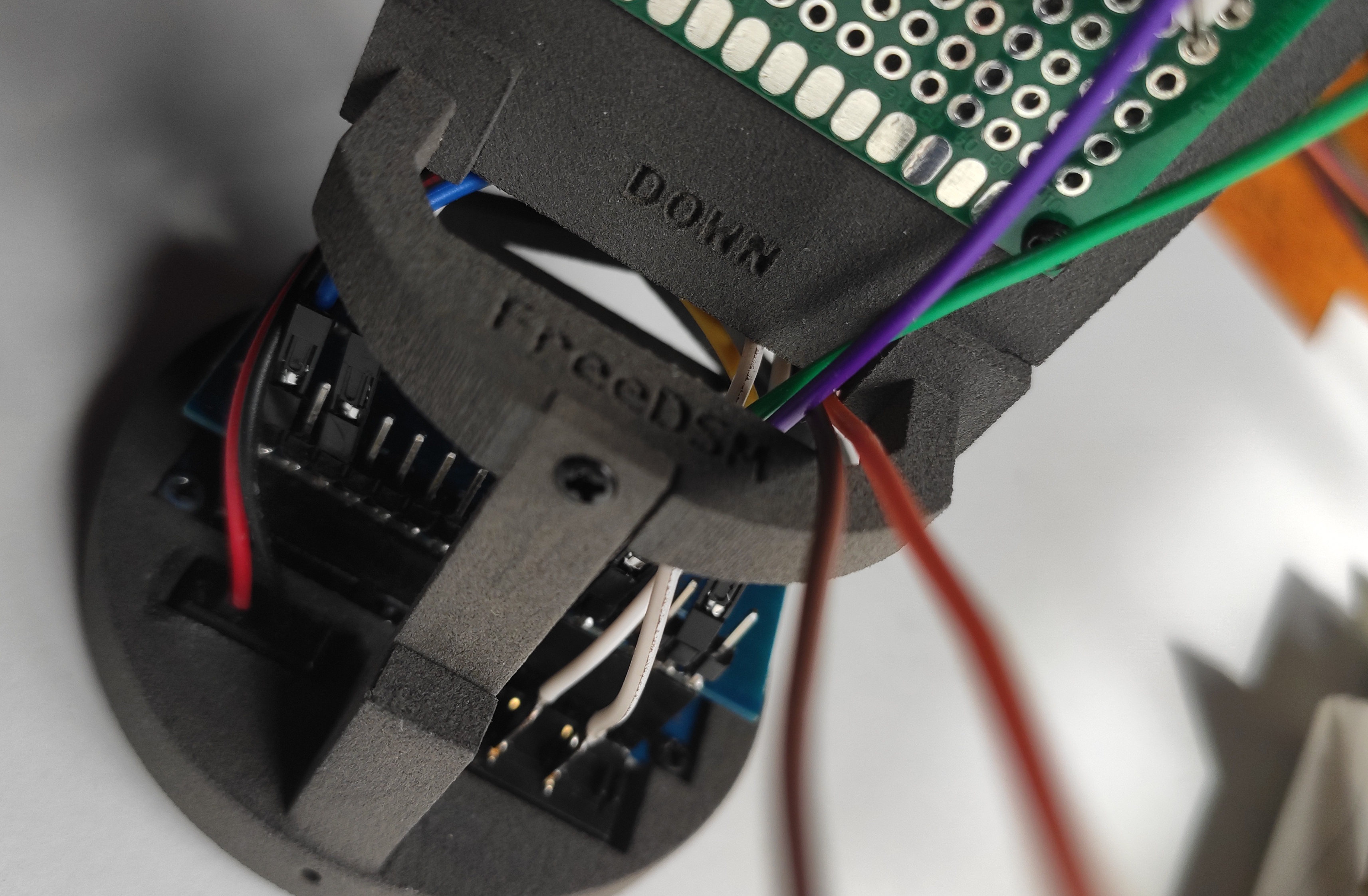
Fix PCB with 4 screws and connect the dupont cables for the sensors: SDA (purple), SDL (green), 3.3V (orange), GND (brown) |
 |
Use one screw to fix the AHT sensor and pass the 4 wires to the PCB side |
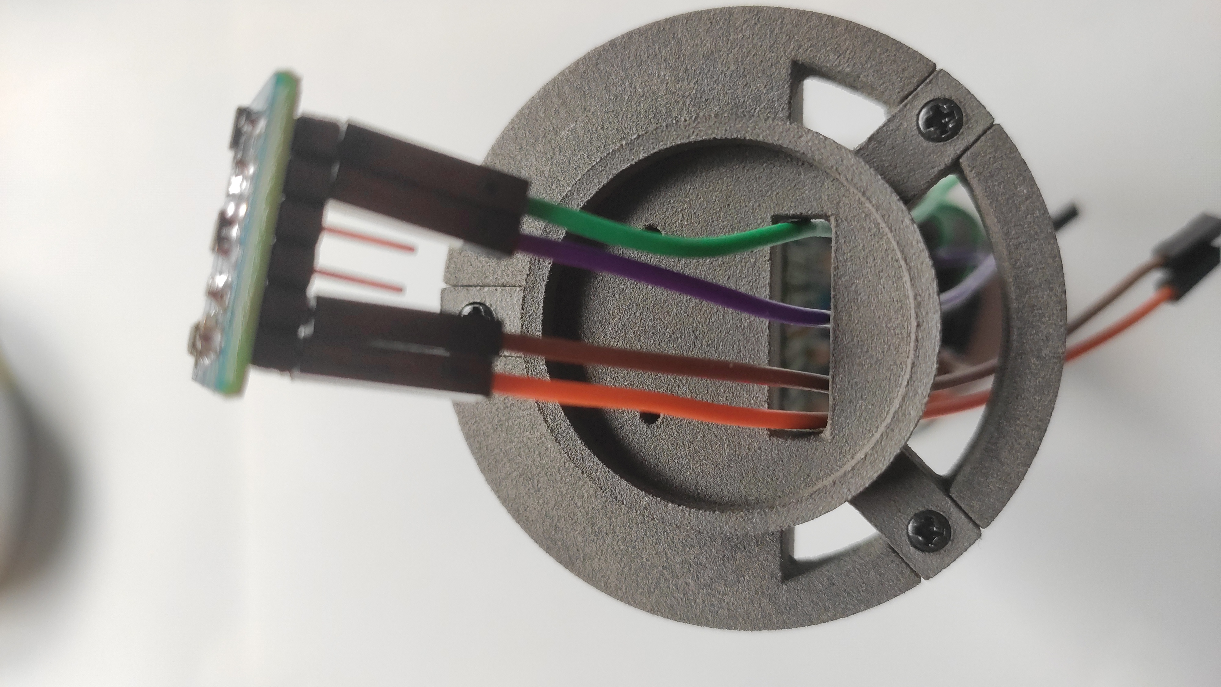 |
Pass the wires of TSL2591 on the top side of the chassis |
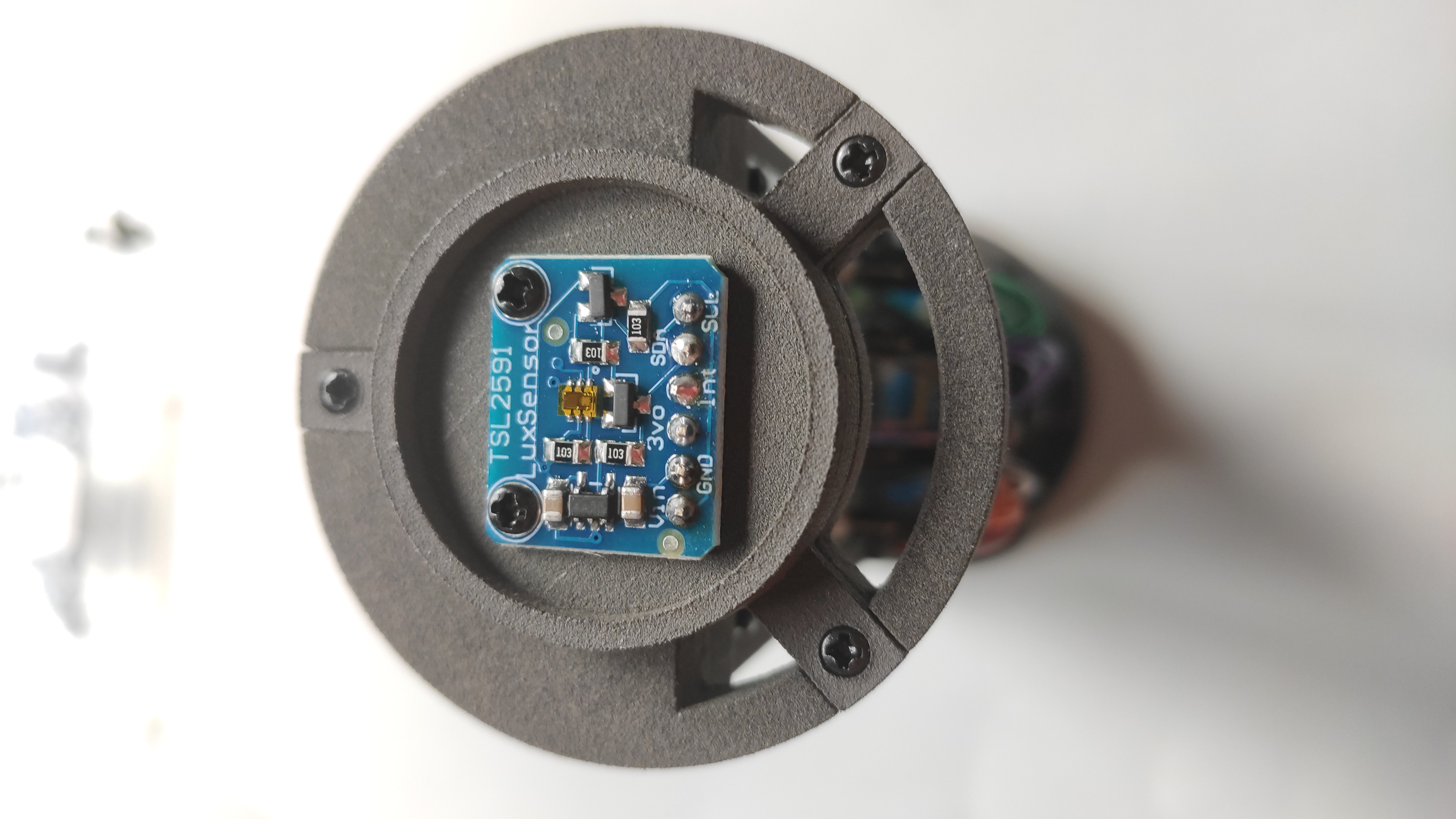 |
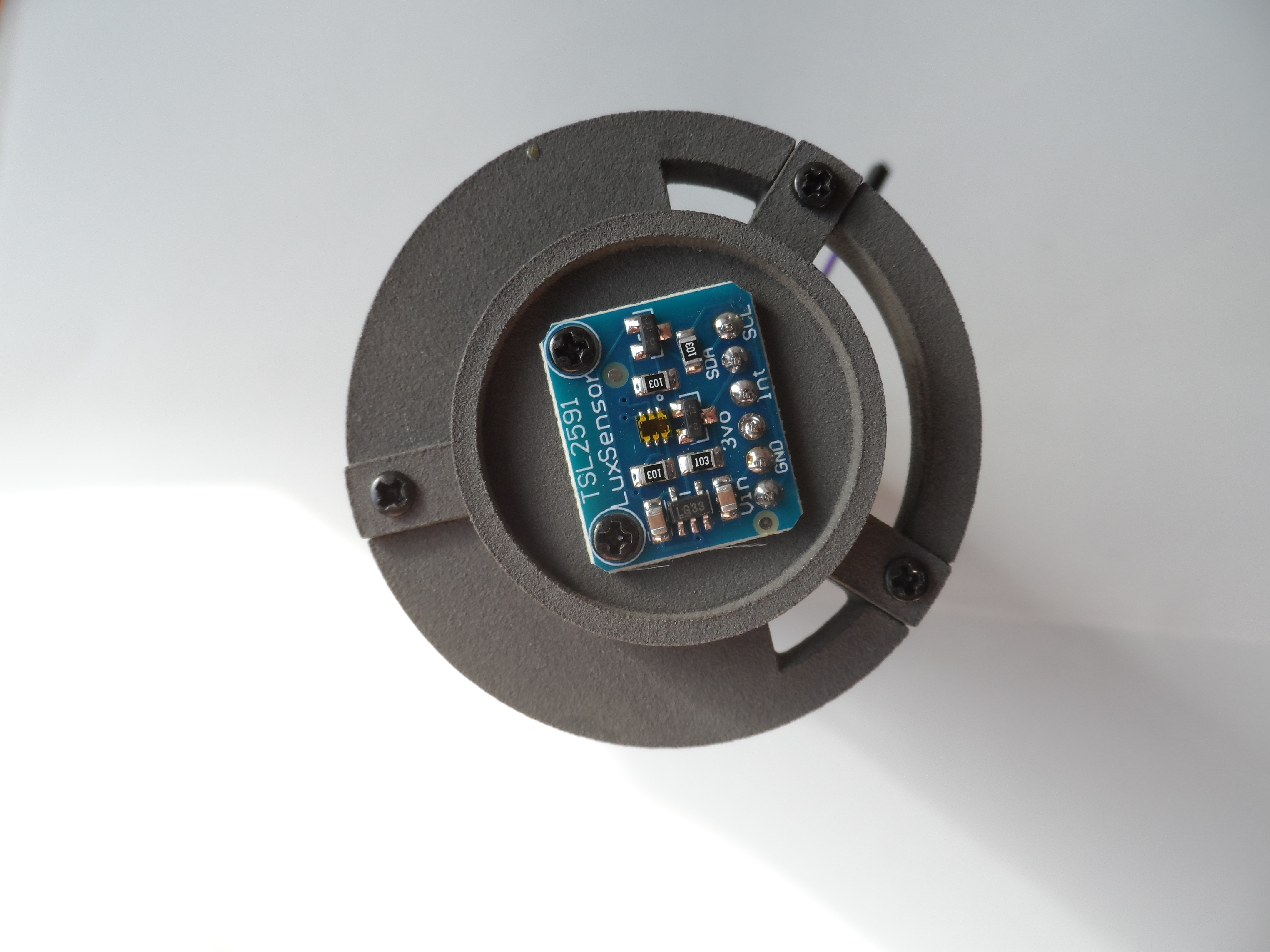
Screw the sensor TSL2591 |
 |
Connect the wires from both sensors in each block of colors |
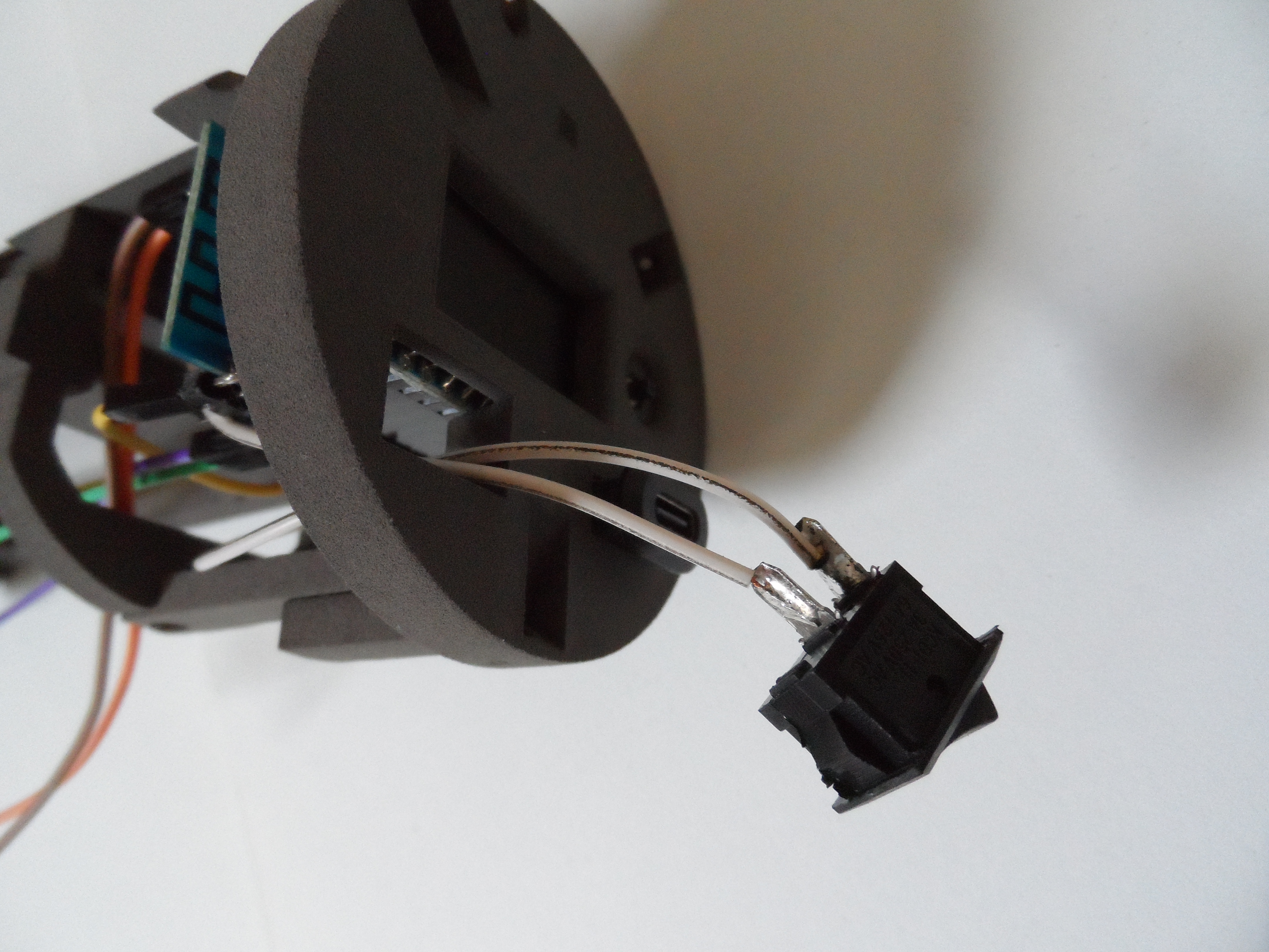 |
Solder both white wires to the switch (one from the GND in the ESP32C3 and the other from the battery charge controller MCP |
 |
Front complete (display, switch and USB-C port) |
 |
Top support for TSL2591 with screws and wires |
 |
Top support fitted in the upper part |
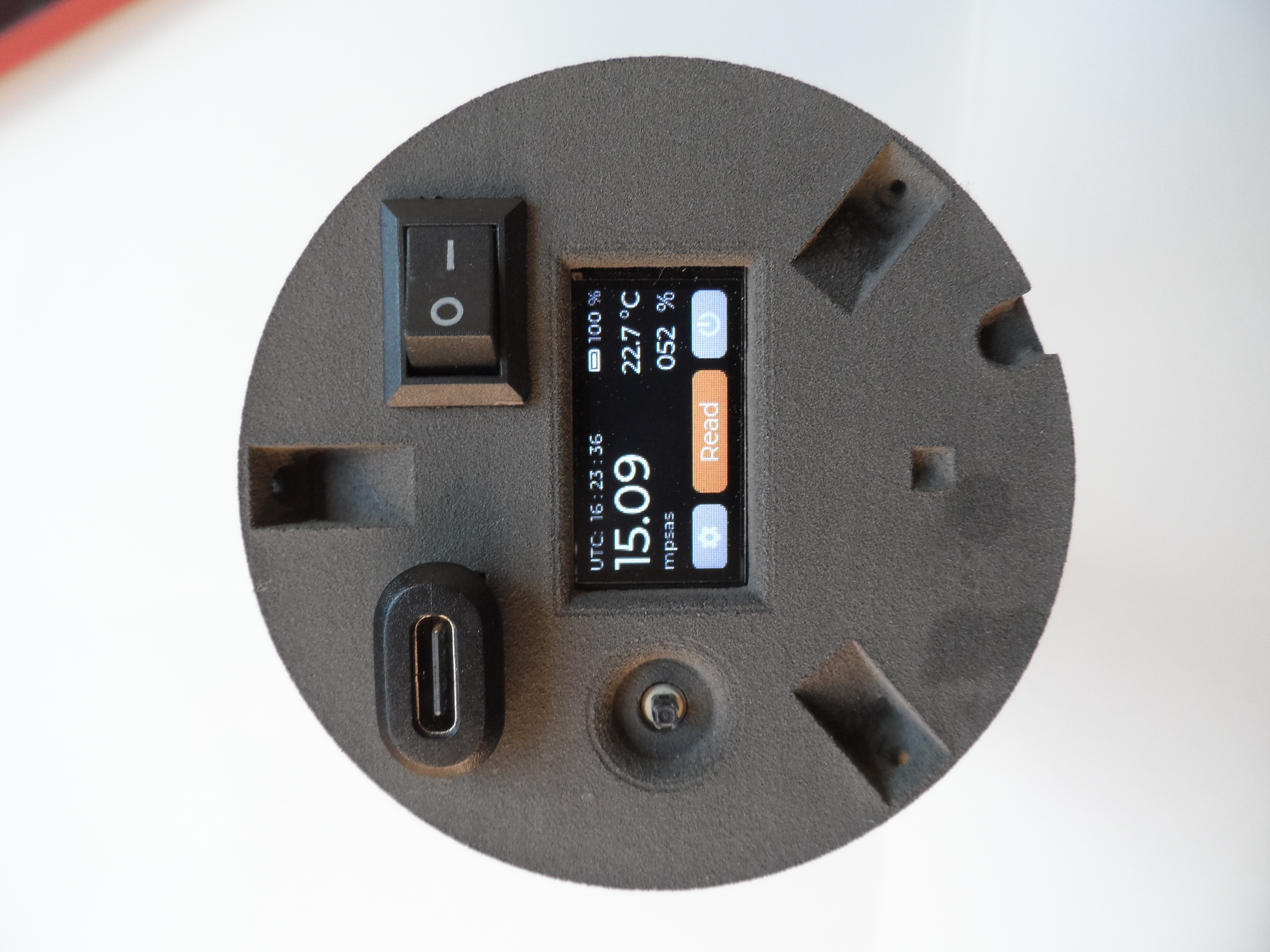 |
Front complete and running with all the sensors |
There is another option for assembling all the internal wiring, without using the PCB or Dupont connector cables. The wires can be soldered directly to the ESP32 processor board. Please note that, on four of the pins, you will need to solder two wires: the power and I2C bus data connections for the light and temperature sensors.
The advantage of this approach is that it reduces the risk of poor connector contacts, as soldered connections are more robust and reliable over time. The following image shows an example of this type of assembly.