| Picture | Description |
|---|---|
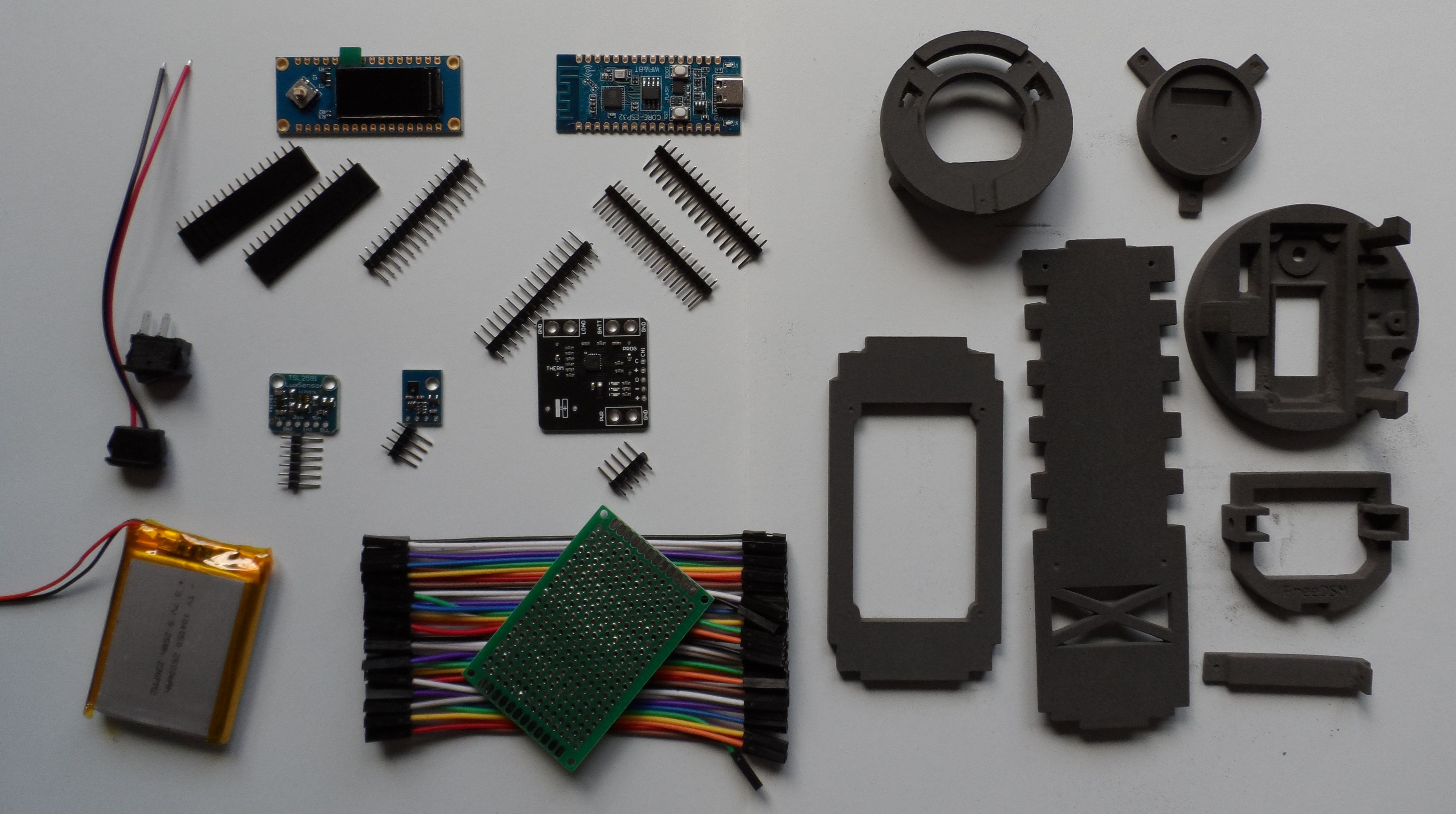 |
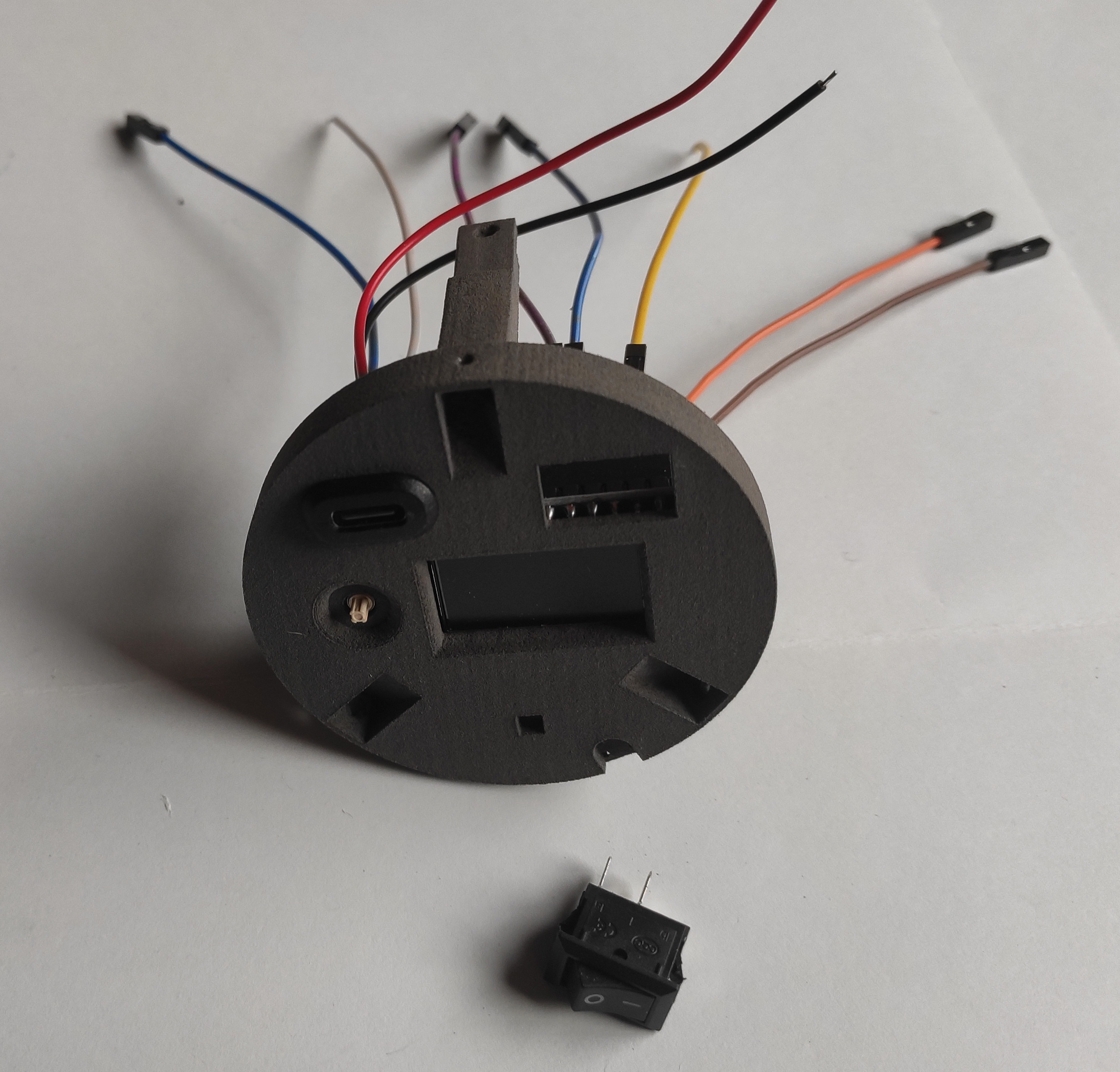
Main components. Additionally, 2 100 Ohm resistors and pin header not in the picture |
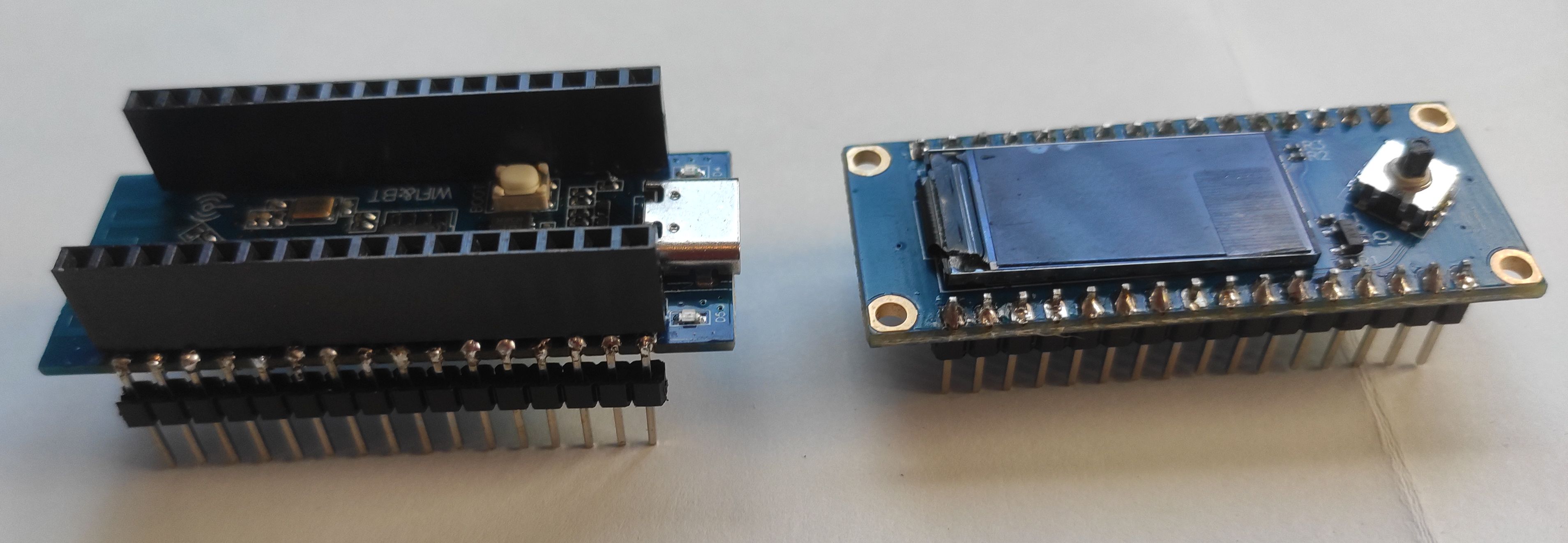 |
Pin soldering ESP32 C3 CORE and Air 101 display |
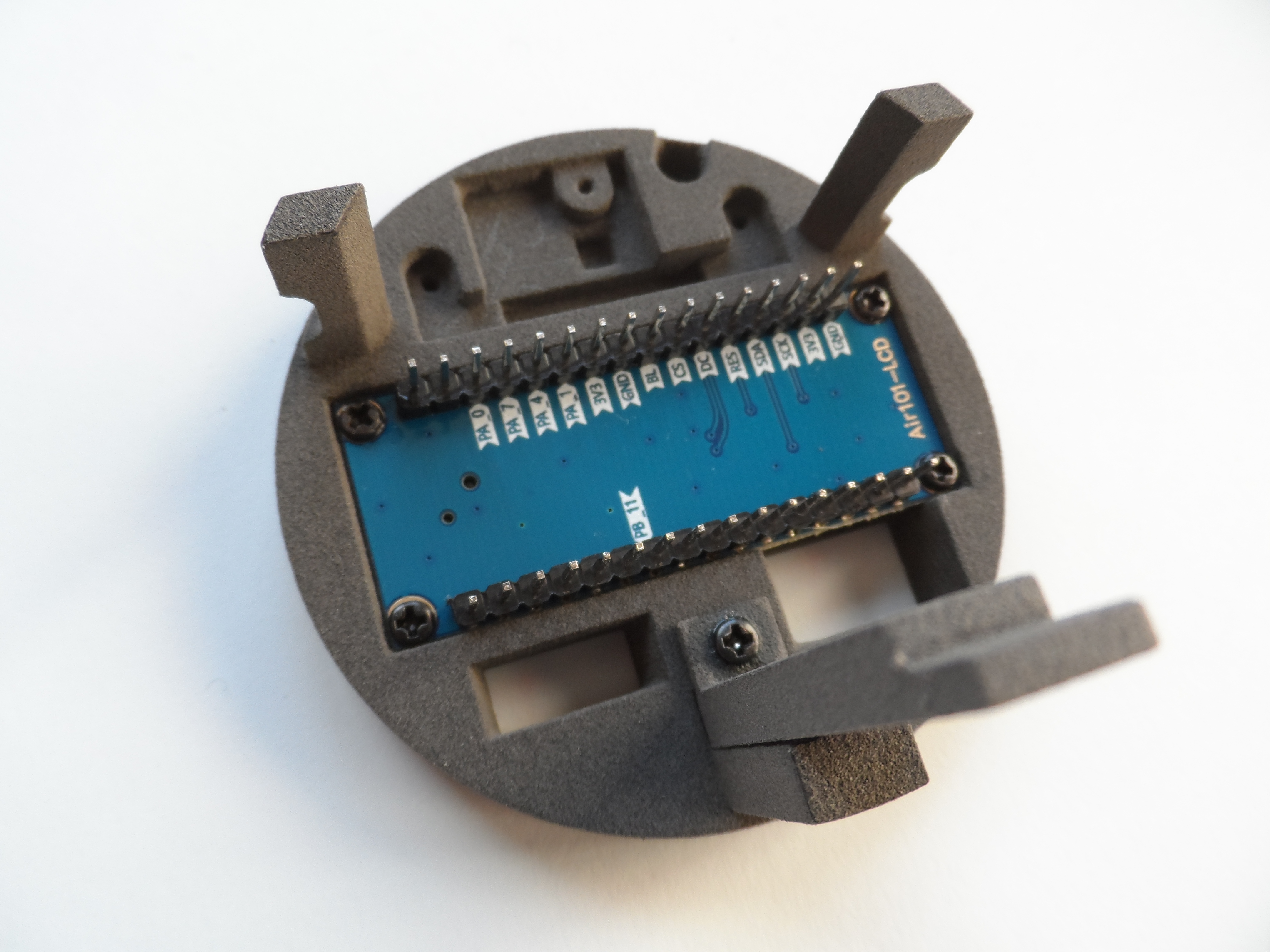 |
Screw the display to the round part |
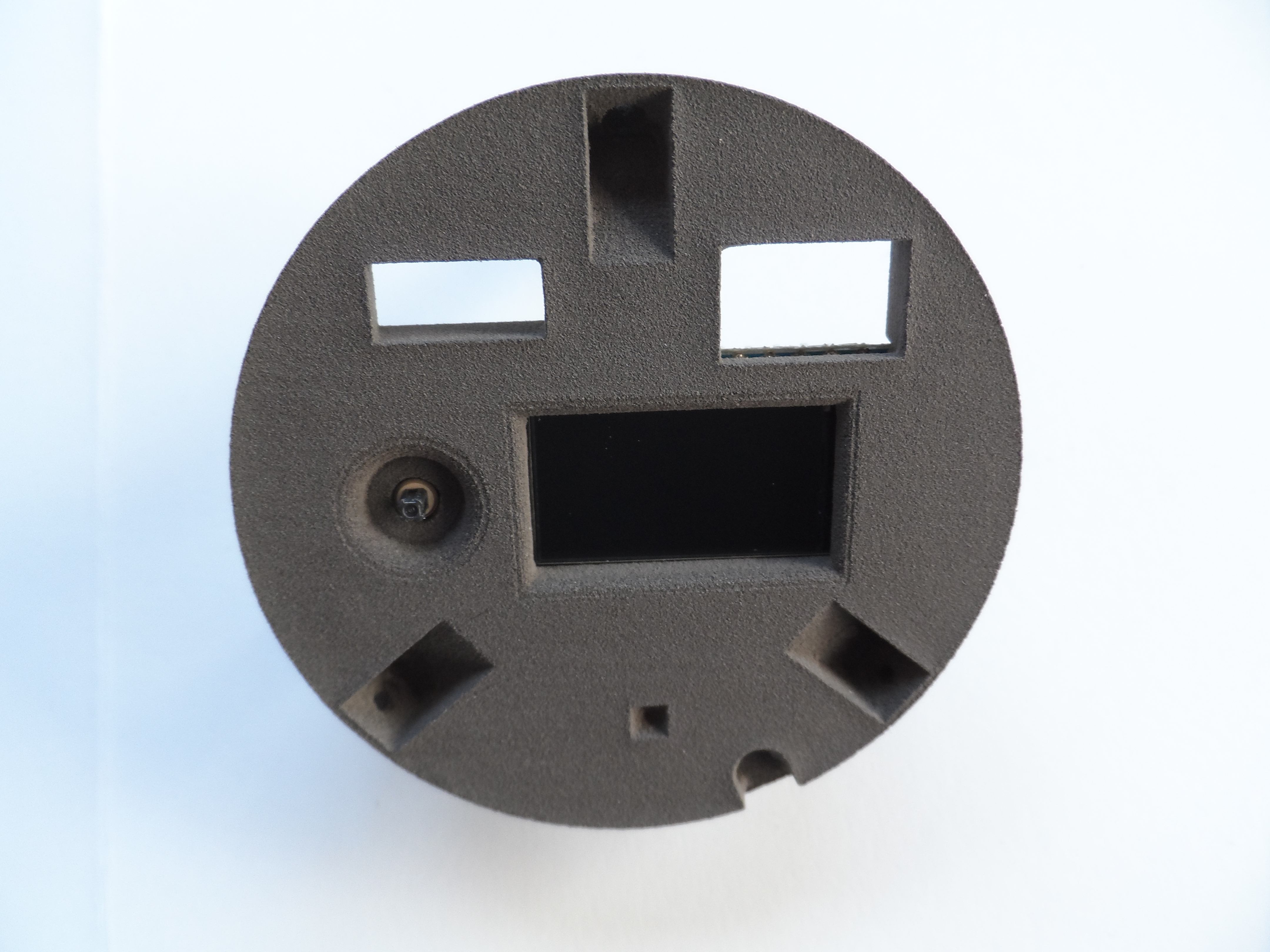 |
This is how it looks from the outside |
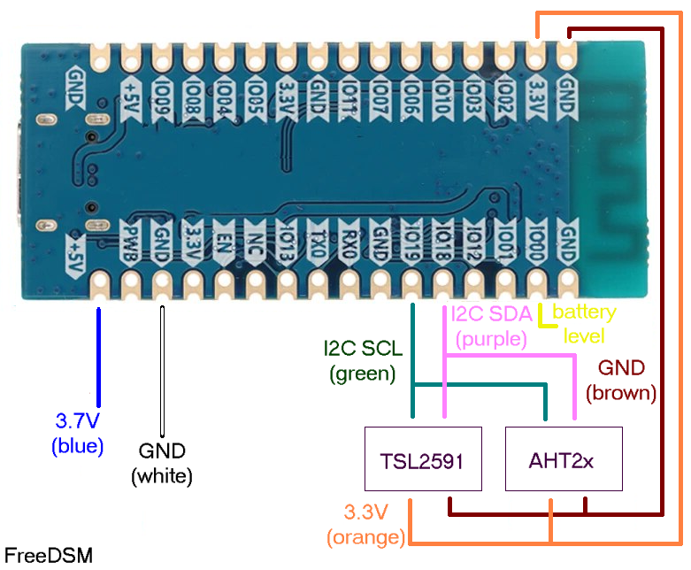 |
Wiring scheme |
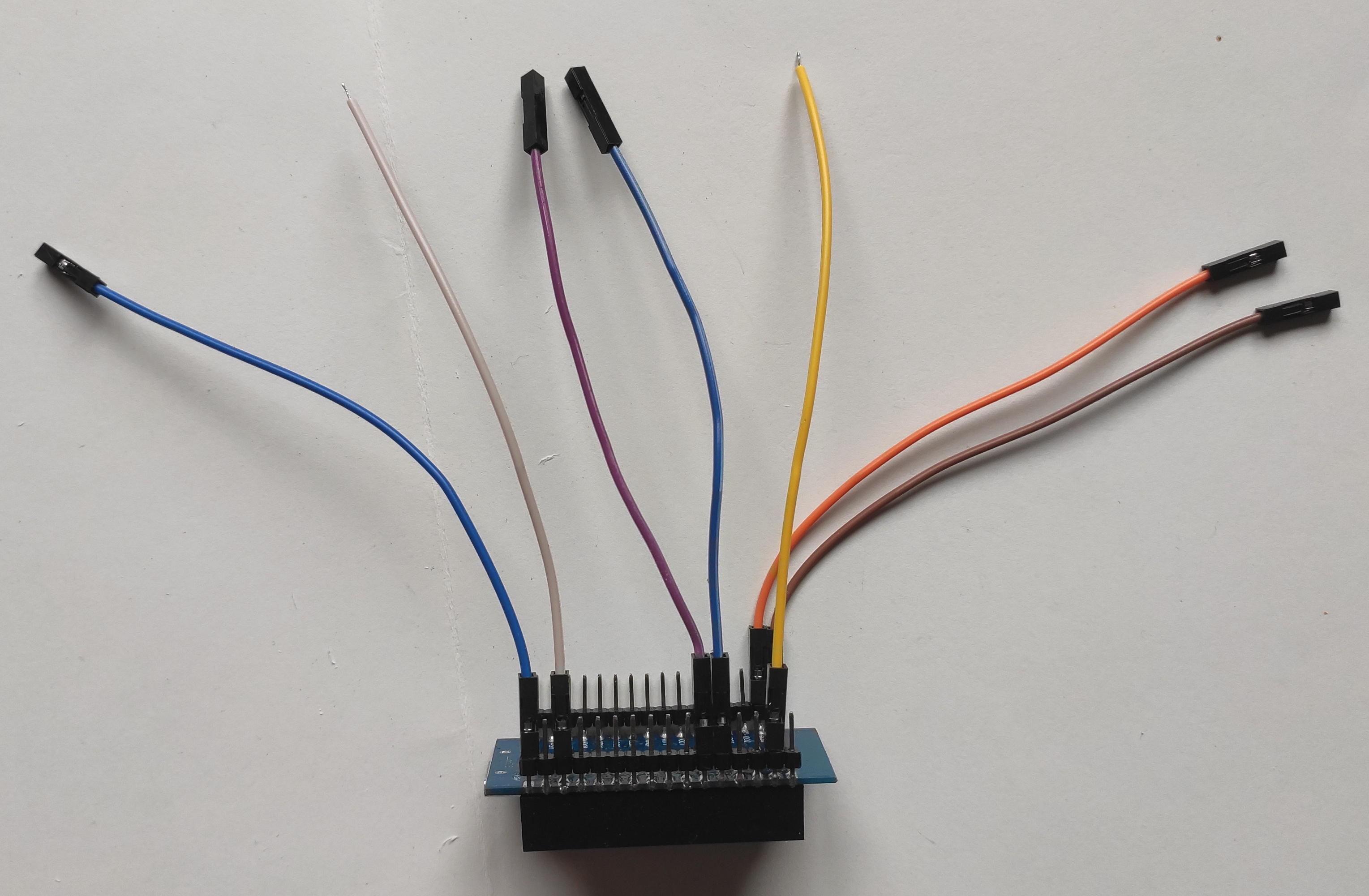 |
Wires connected to the ESP32 |
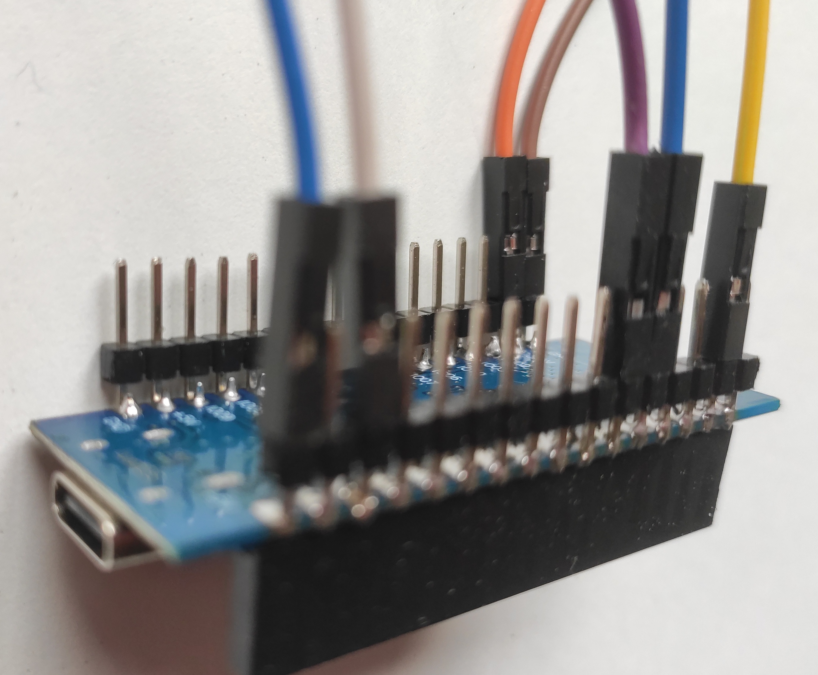 |
A more detailed picture of the connections to the ESP32 |
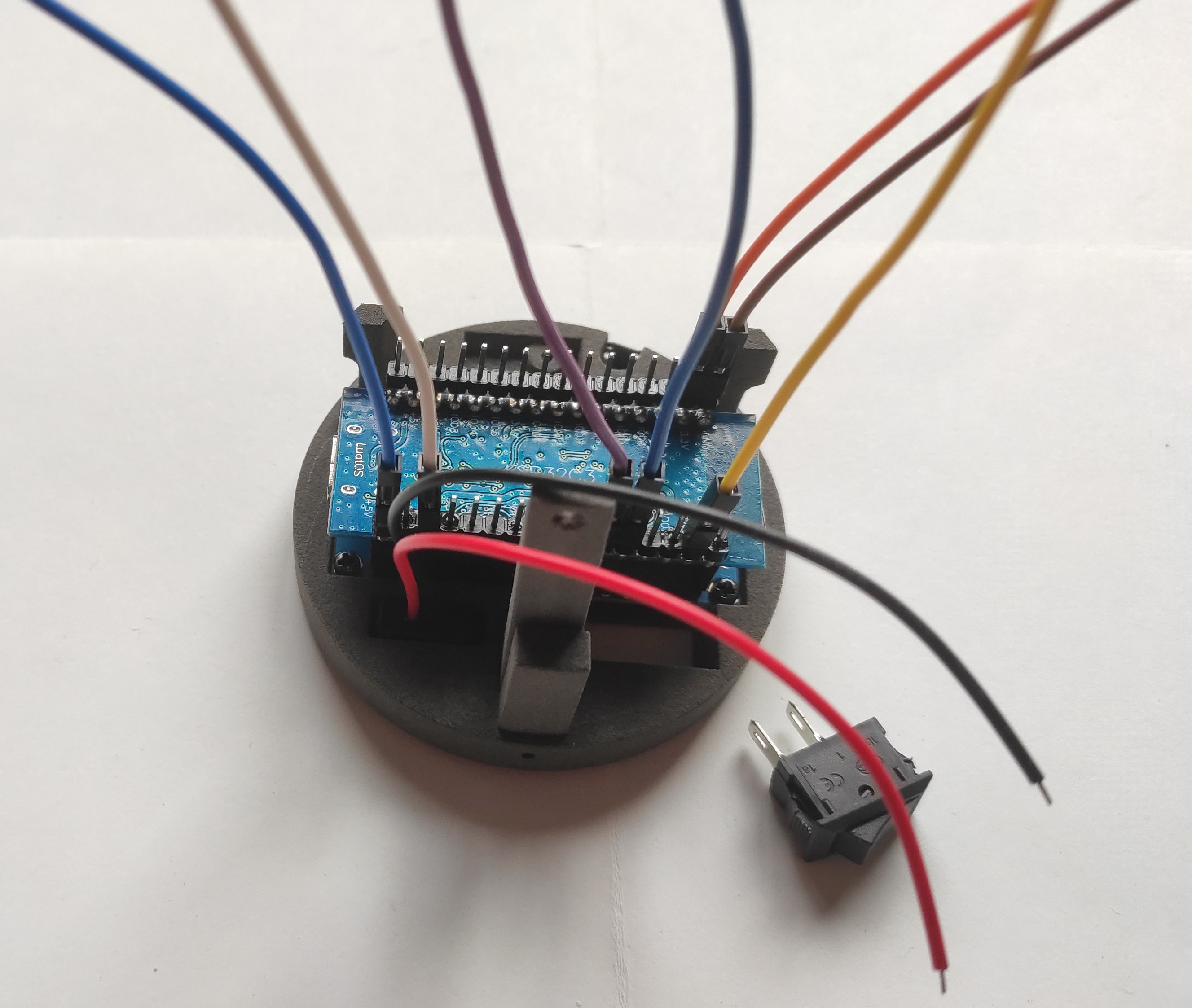 |
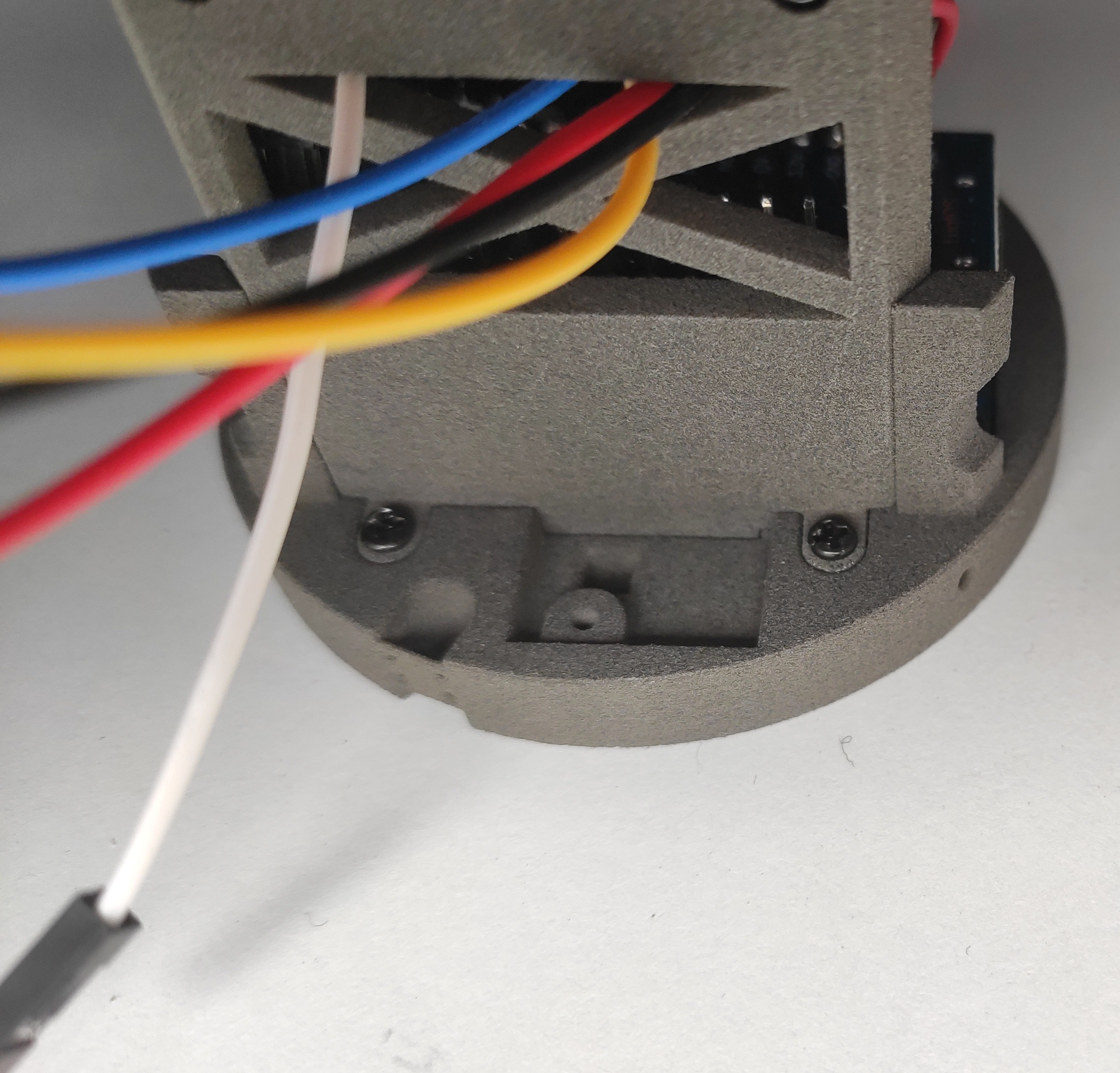
ESP32 mounted on the round part |
 |
Front of the round part with display and USB-C, wired in the back |
 |
Chassis mounted, except TSL2591 top support and round front (display) |
 |
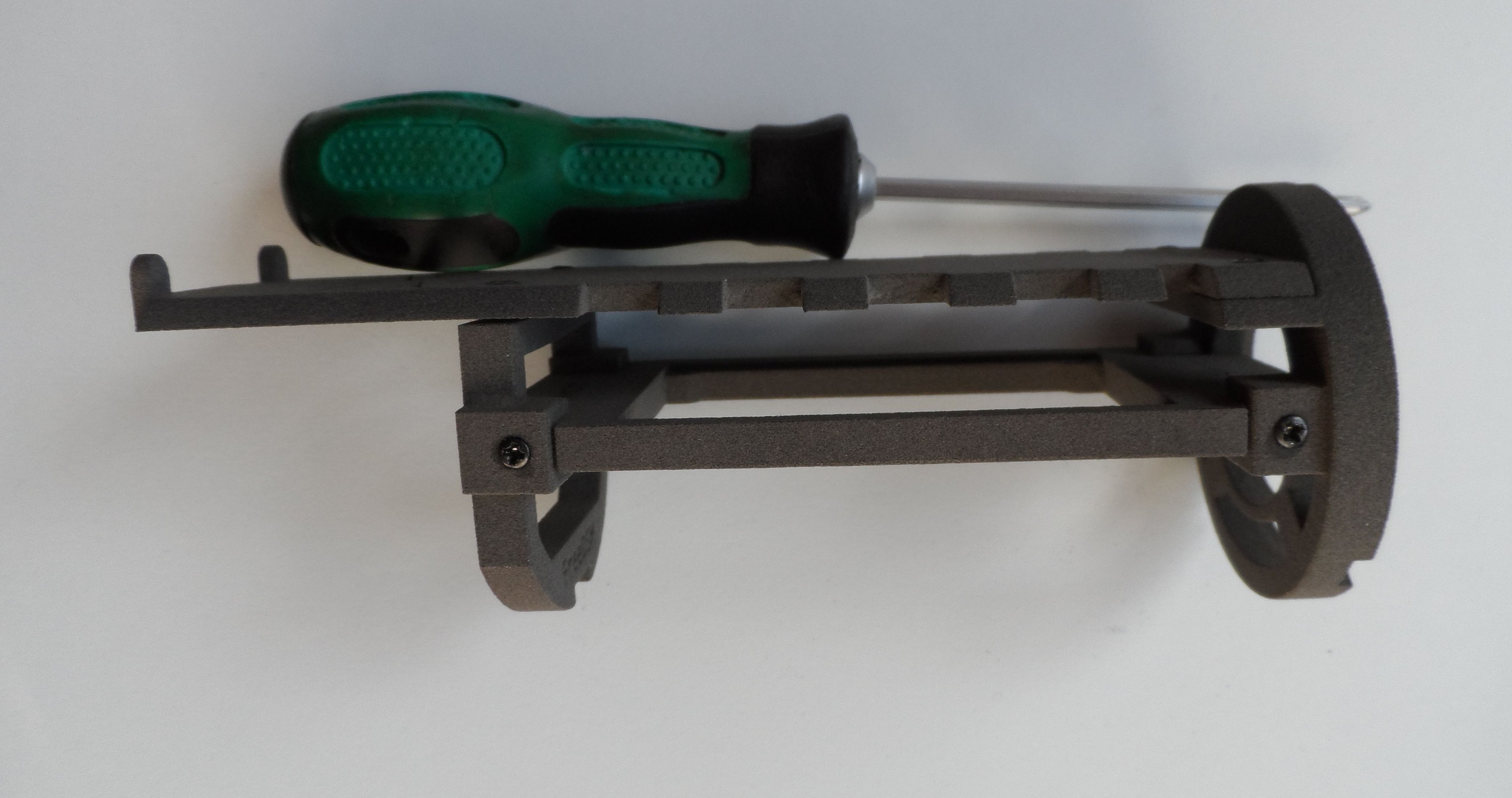
Complete chassis with wires |
 |
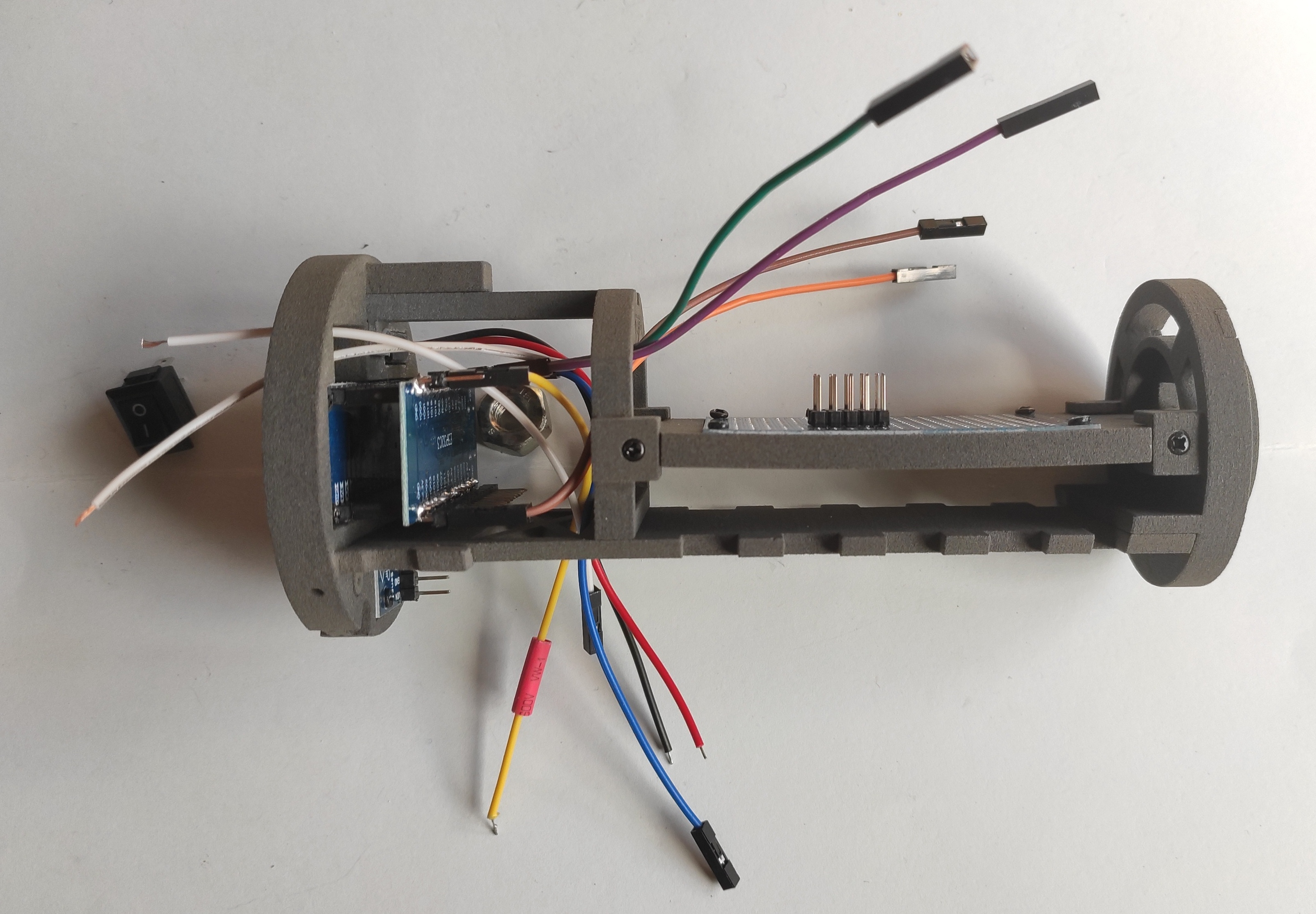
Complete chassis with wires (PCB side) |
 |
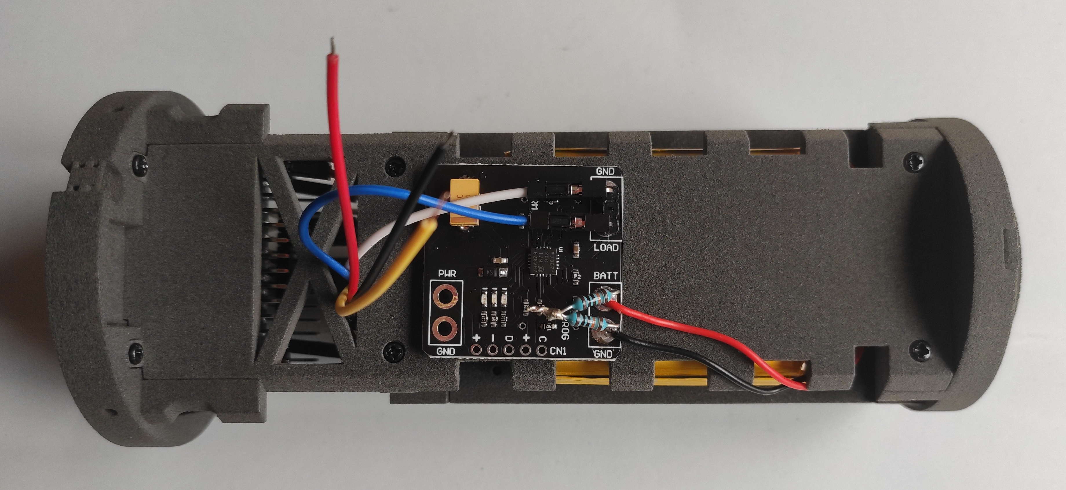
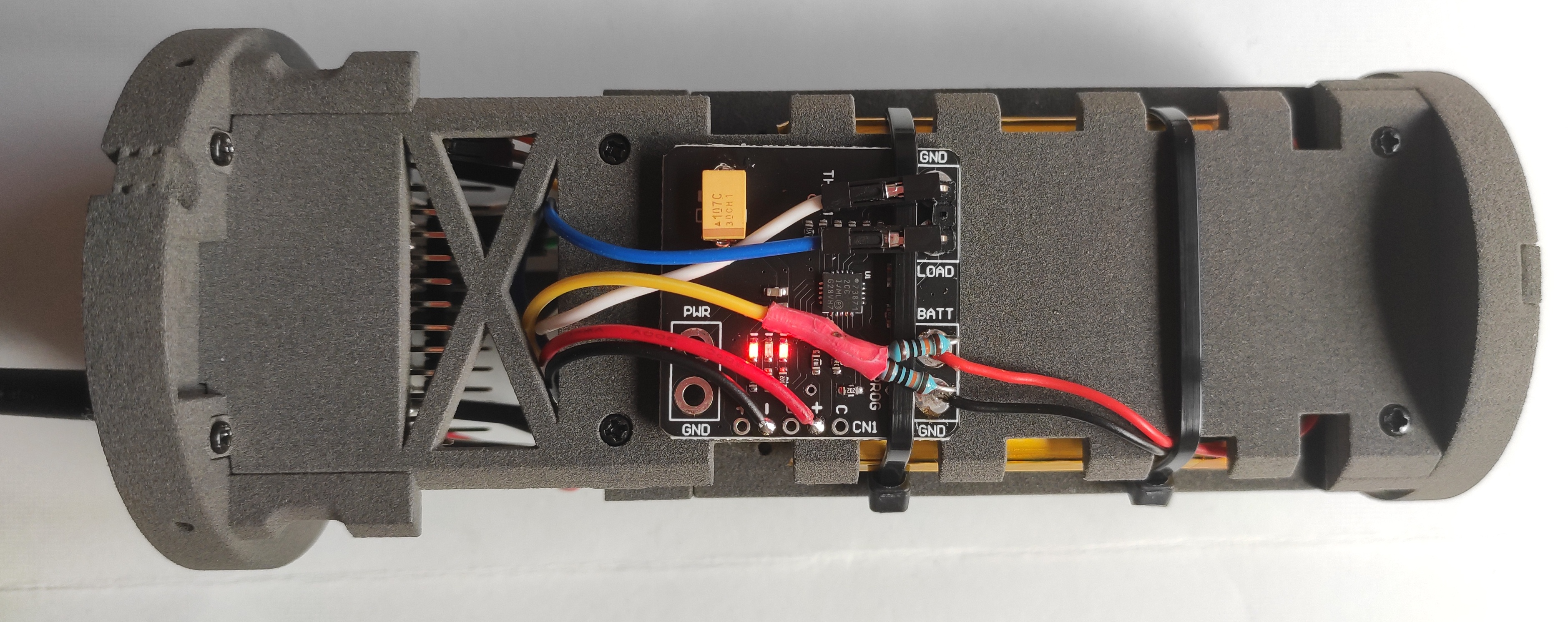
Complete chassis with wires (charge regulator side) |
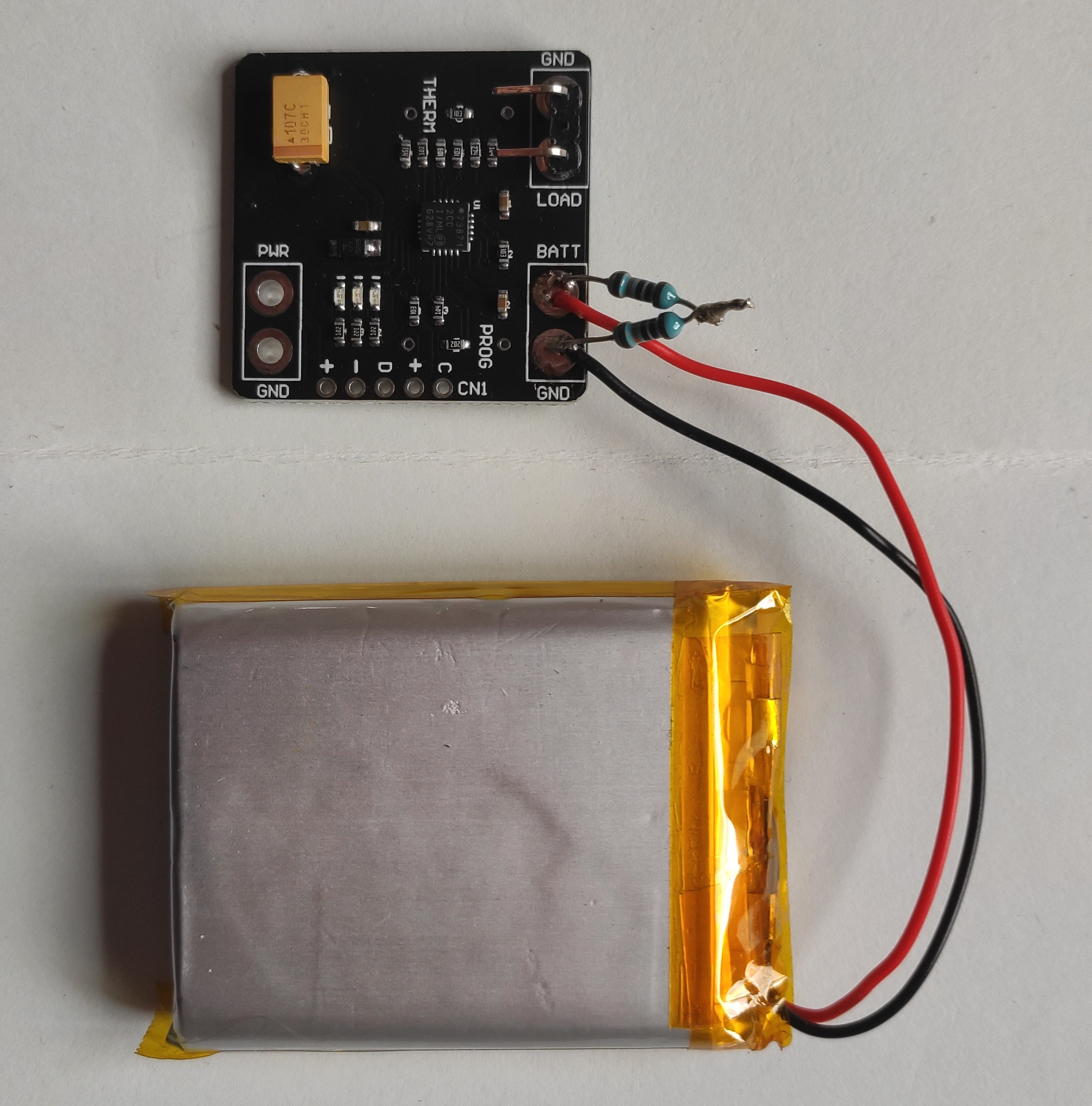 |
MCP battery charge controller |
 |
MCP connections detail |
 |
Stick battery and regulator with double side tape and connect the Dupont connectors LOAD(blue) and GND (white) |
 |
Solder USB-C wires and yellow wire for battery monitoring (protected with tape) |
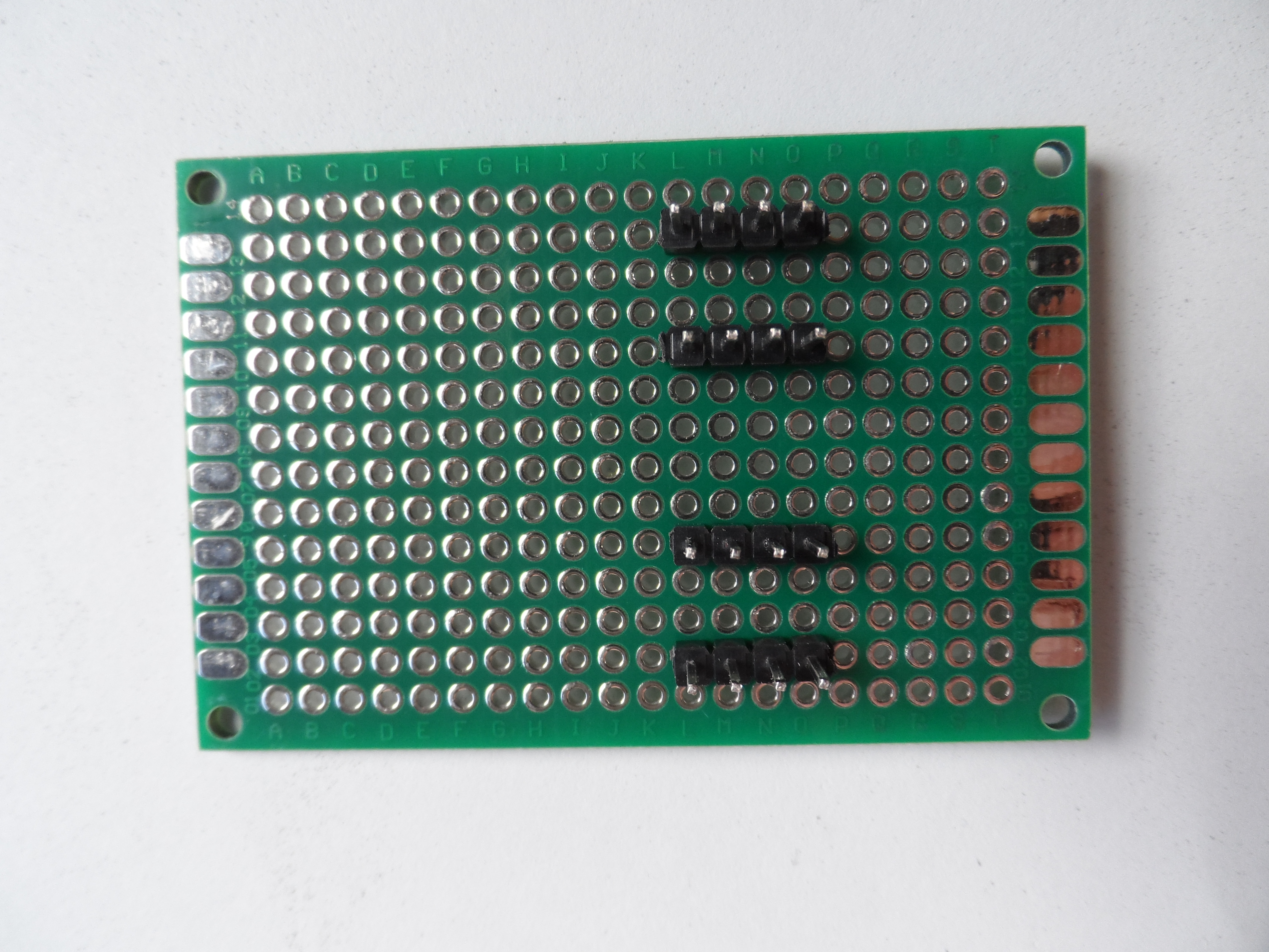 |
Prepare the PCB with 4 blocks of 4 pins. Here is the PCB front, with connections for 3.3V / GND / SCL / SDA |
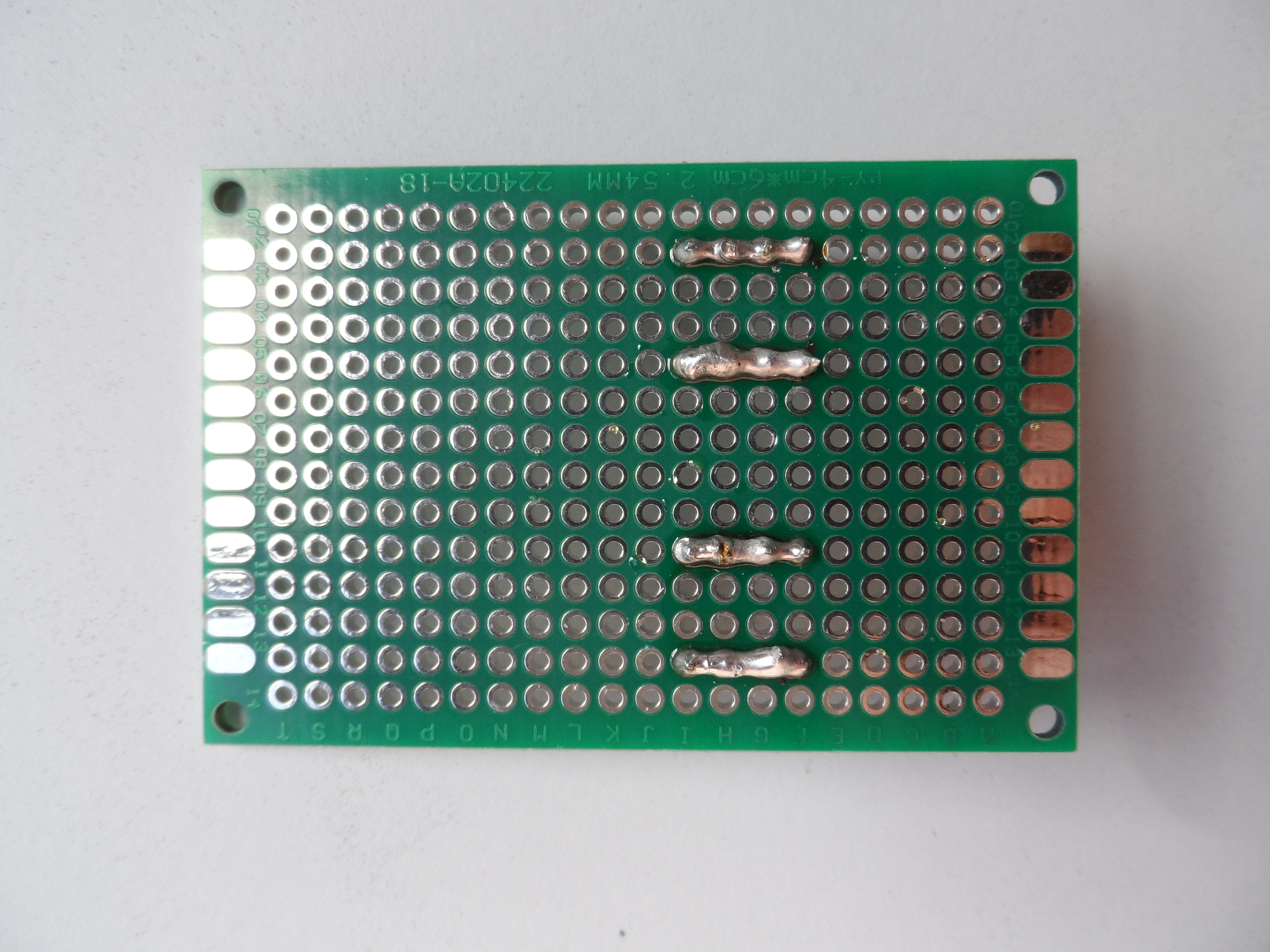 |
PCB back, joined pins of each block |
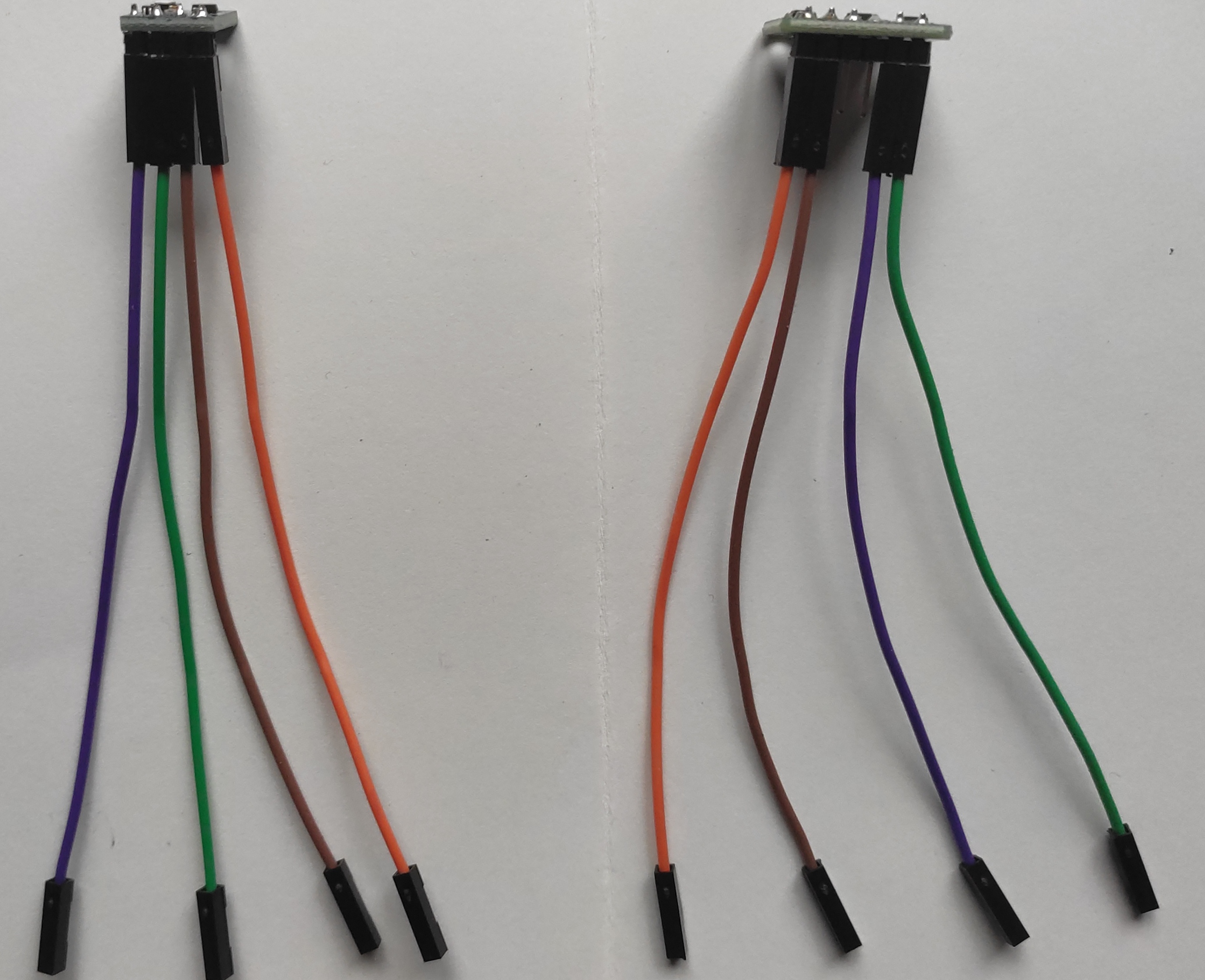 |
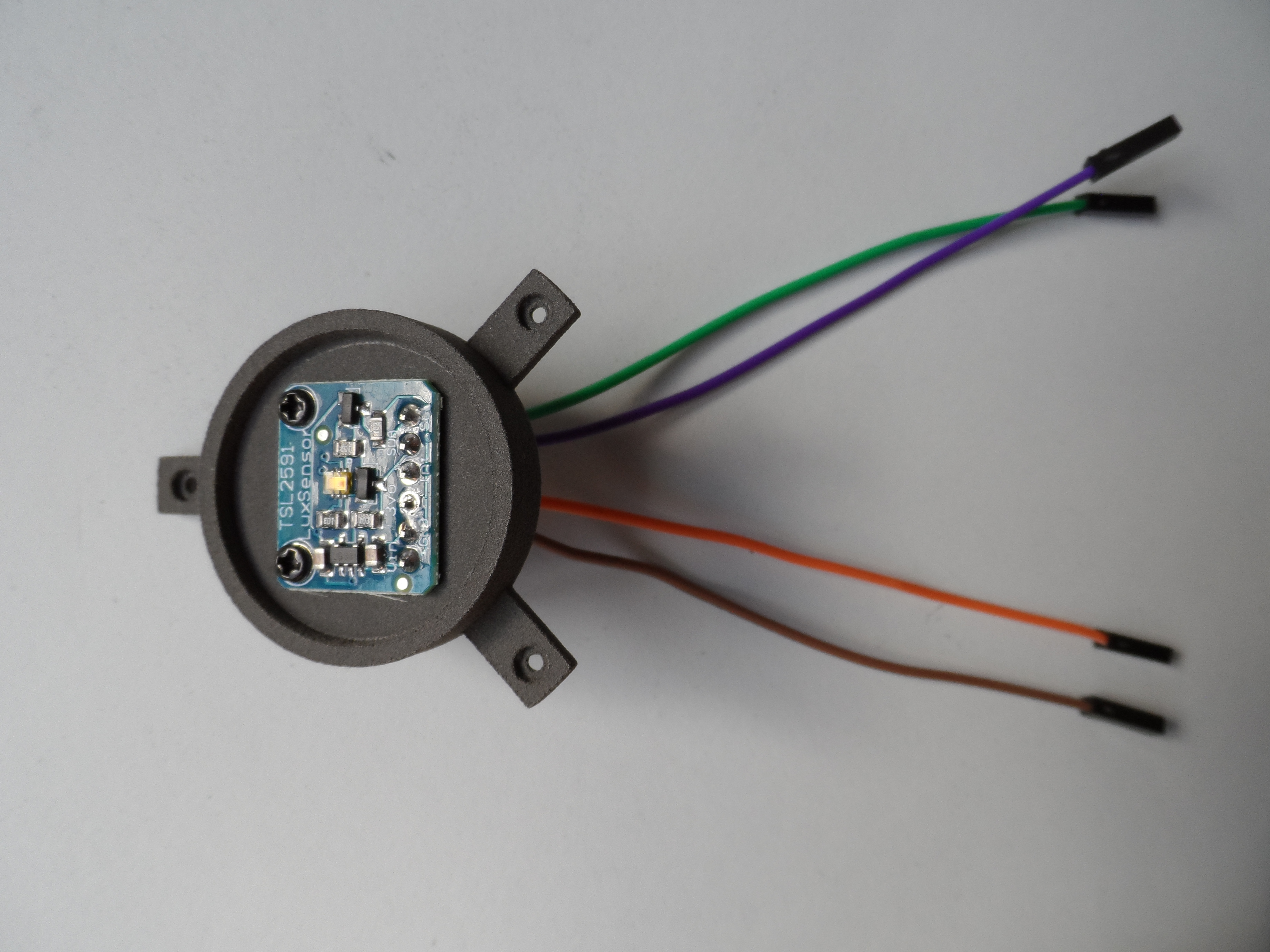
TSL2591 and AHT21 with wires |
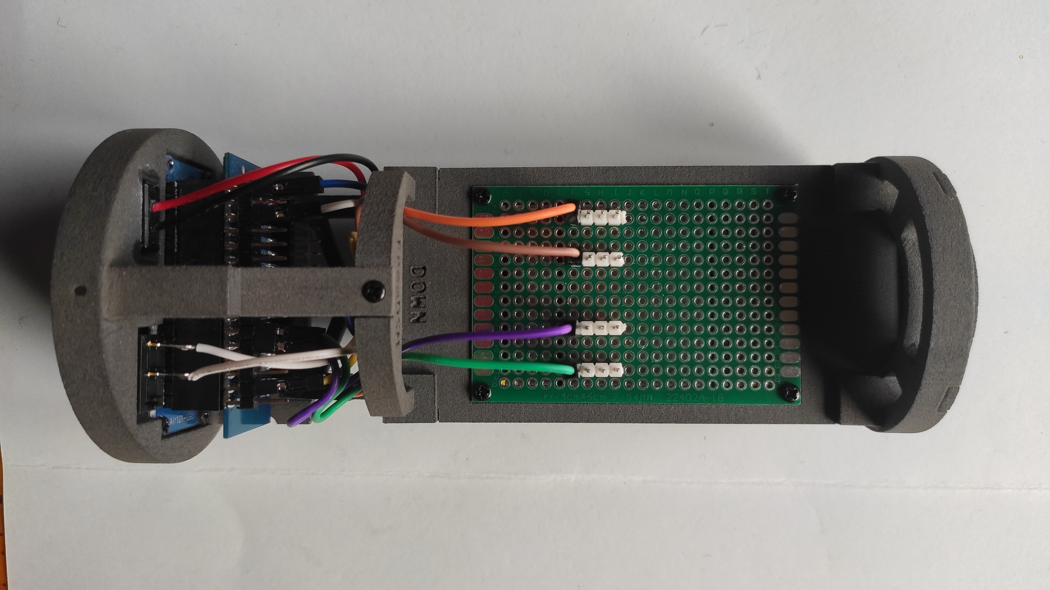 |
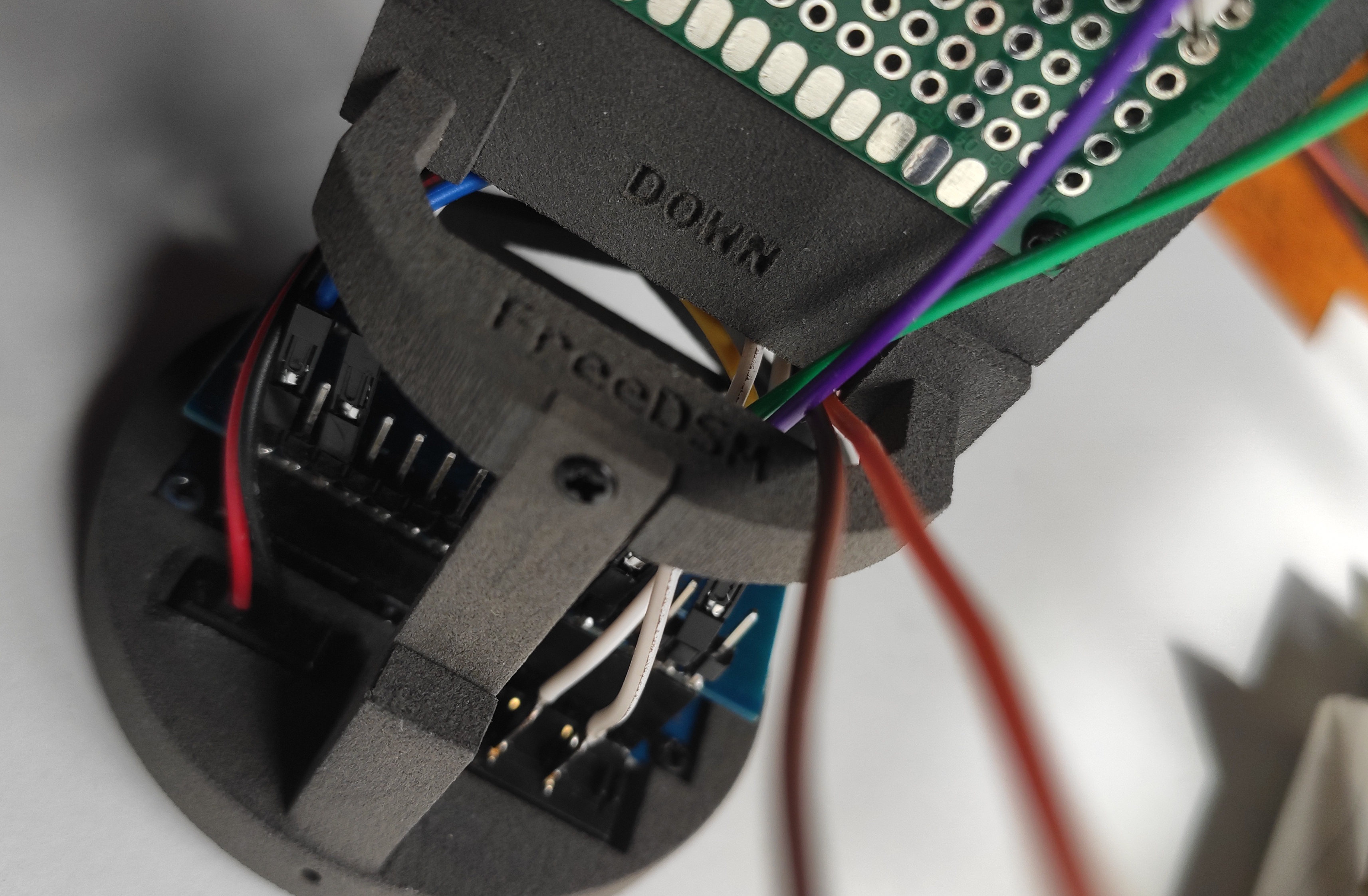
Fix PCB with 4 screws and connect the dupont cables for the sensors: SDA (purple), SDL (green), 3.3V (orange), GND (brown) |
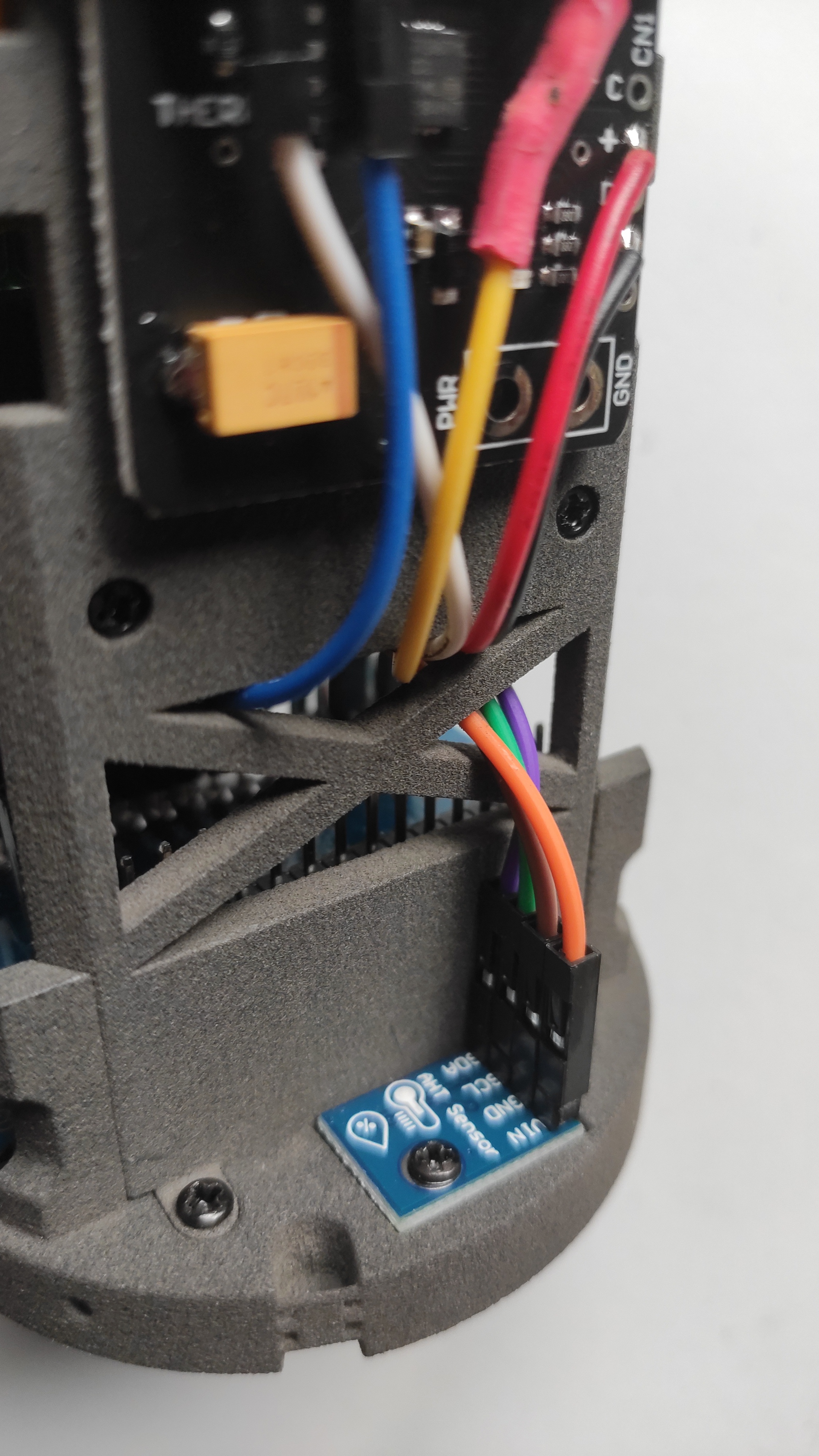 |
Use one screw to fix the AHT sensor and pass the 4 wires to the PCB side |
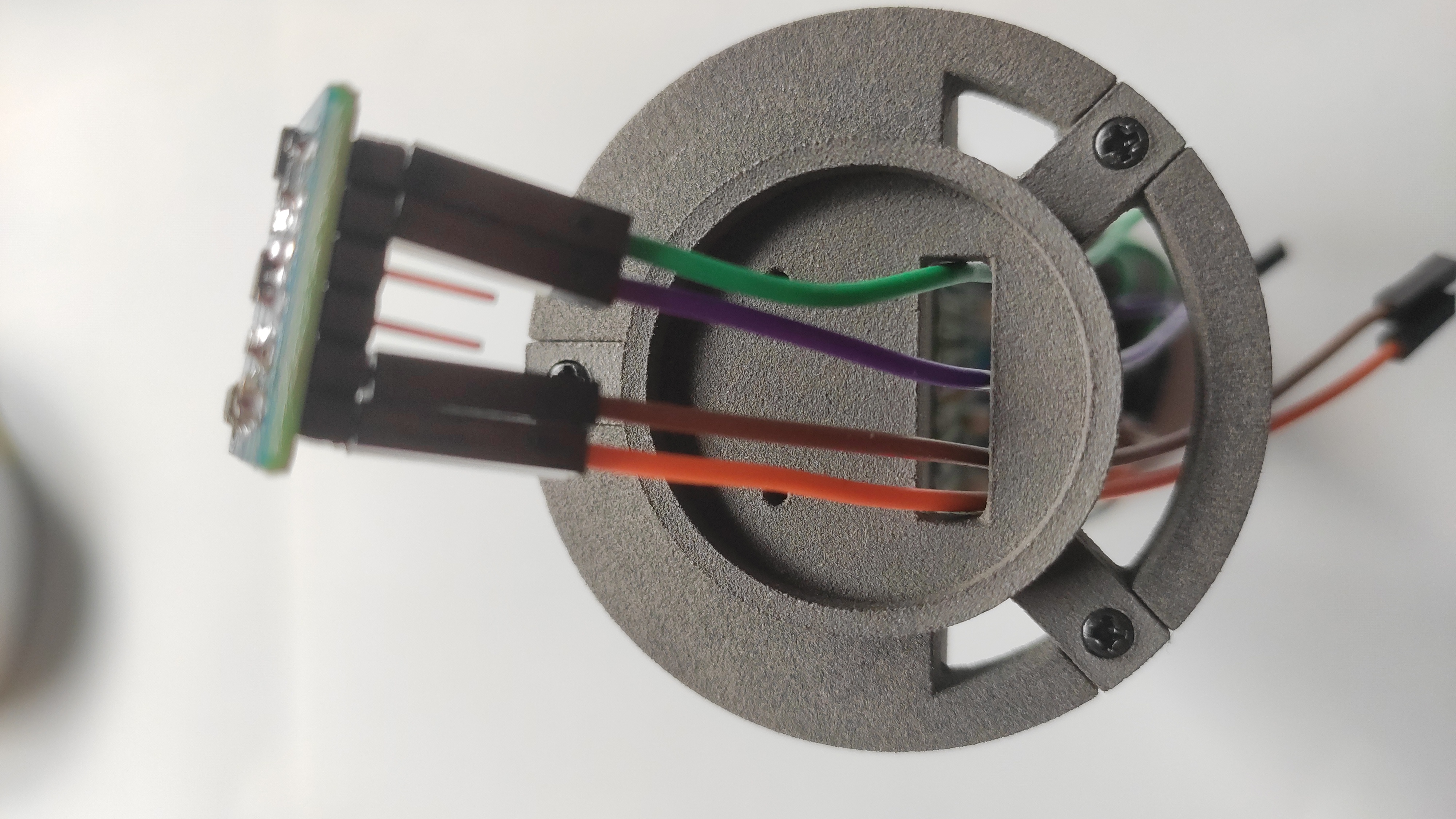 |
Pass the wires of TSL2591 on the top side of the chassis |
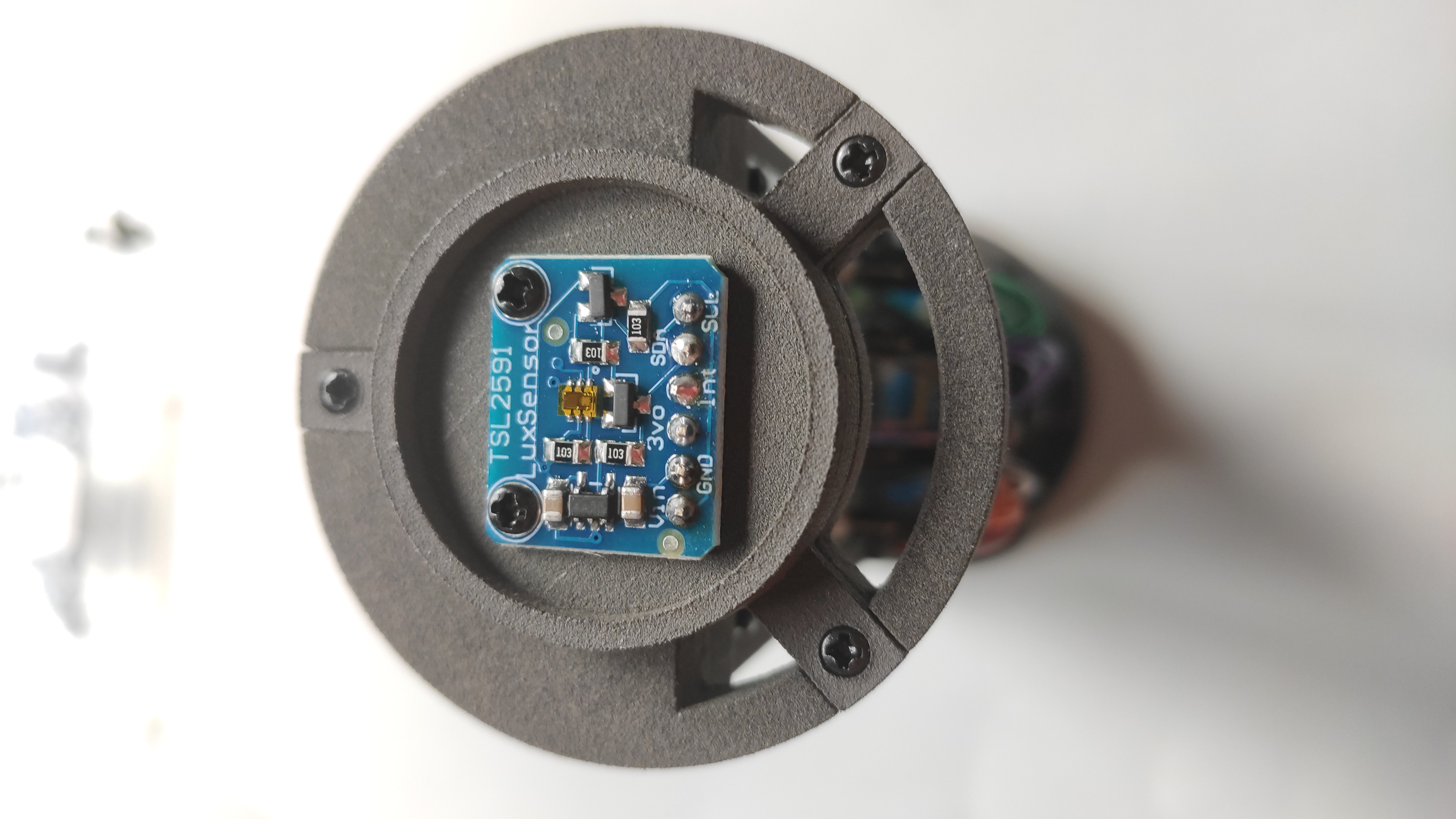 |
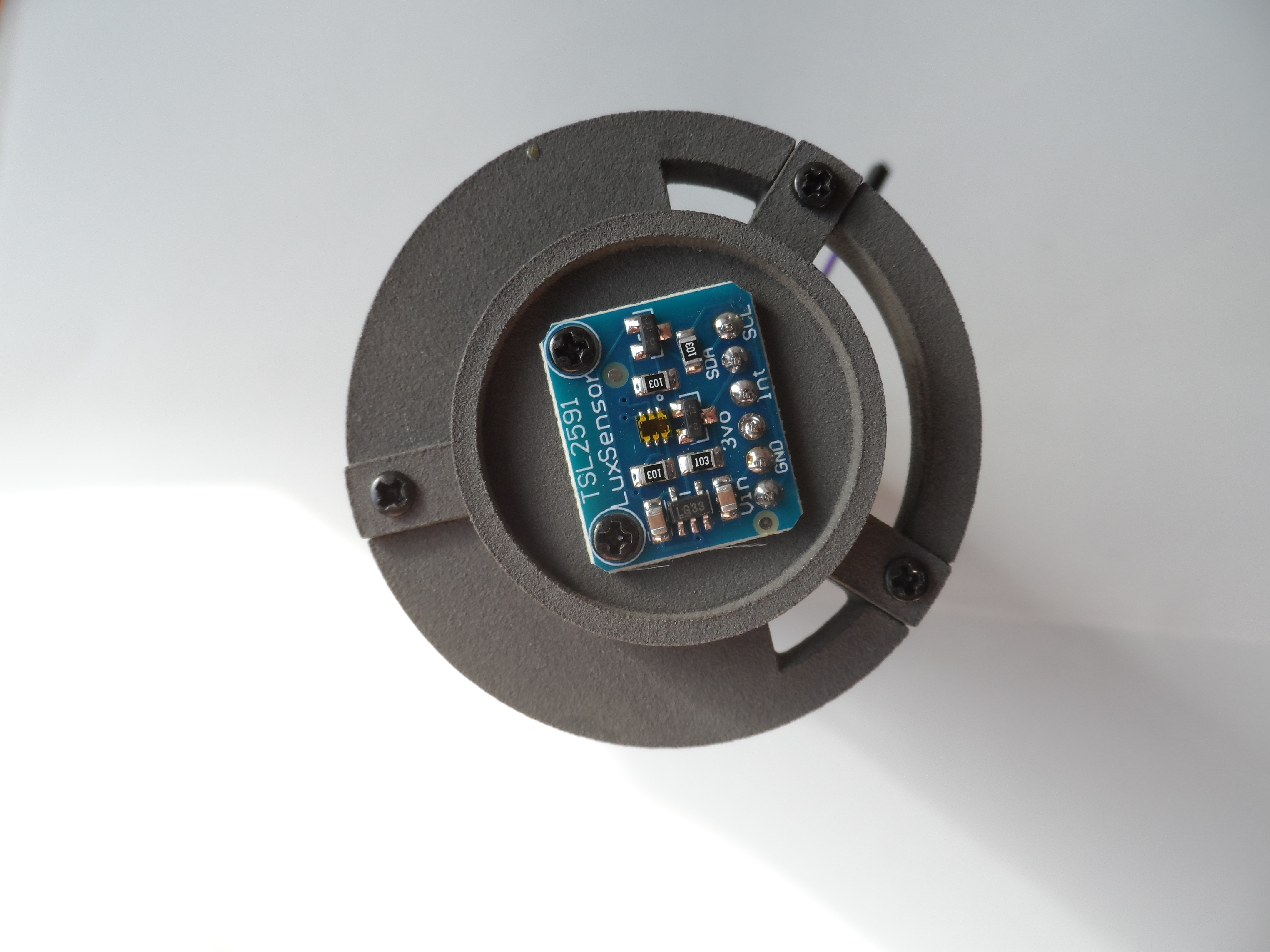
Screw the sensor TSL2591 |
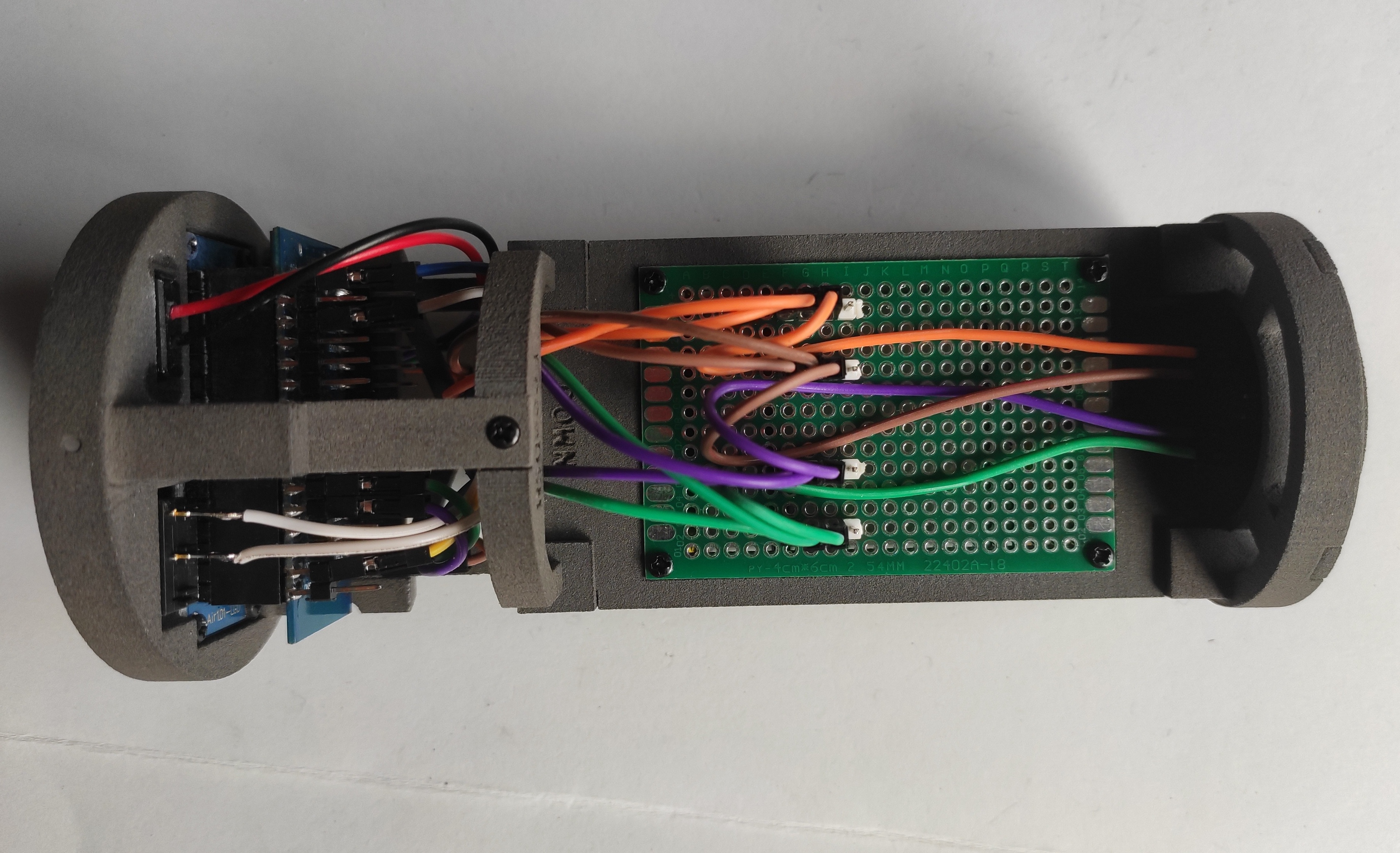 |
Connect the wires from both sensors in each block of colors |
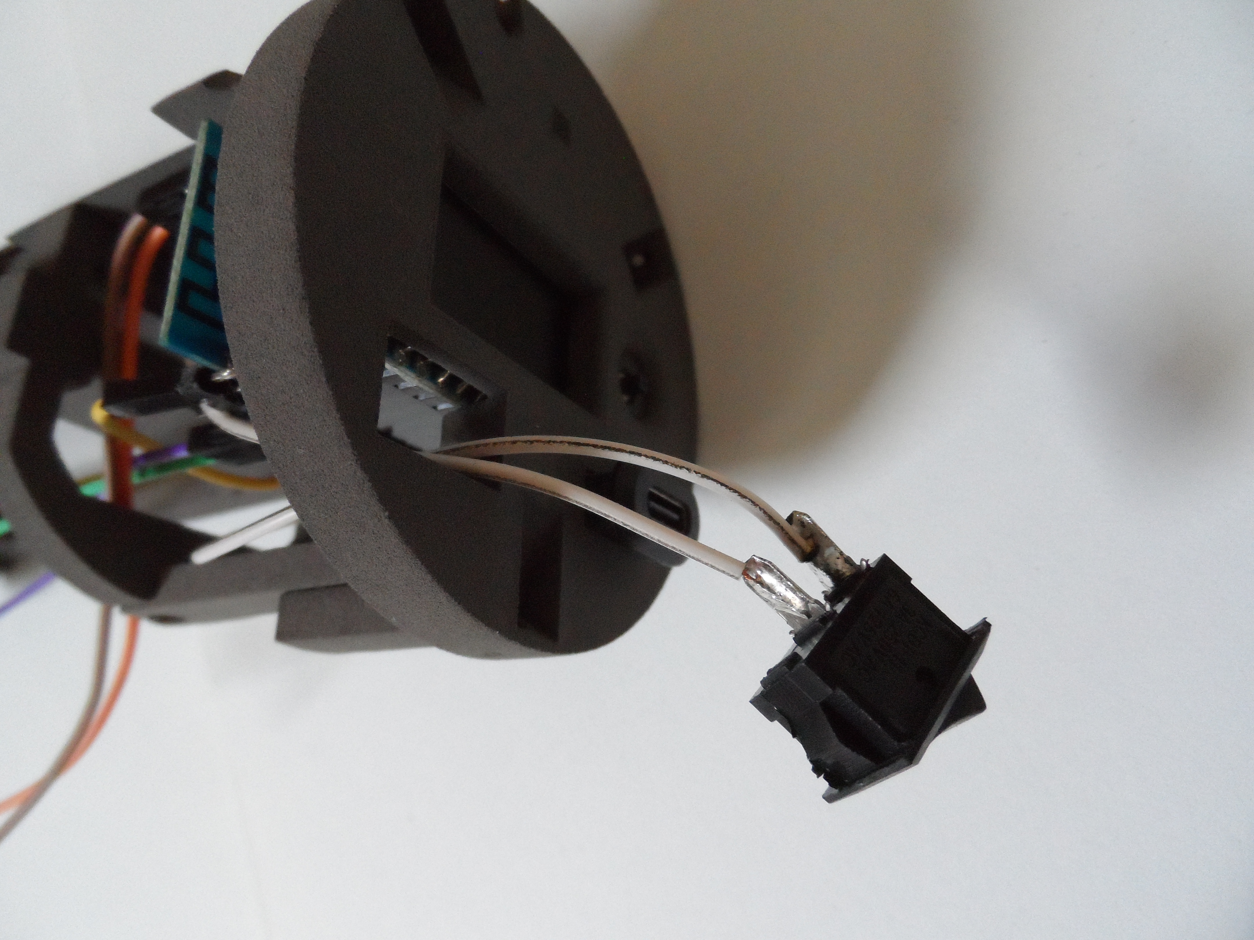 |
Solder both white wires to the switch |
 |
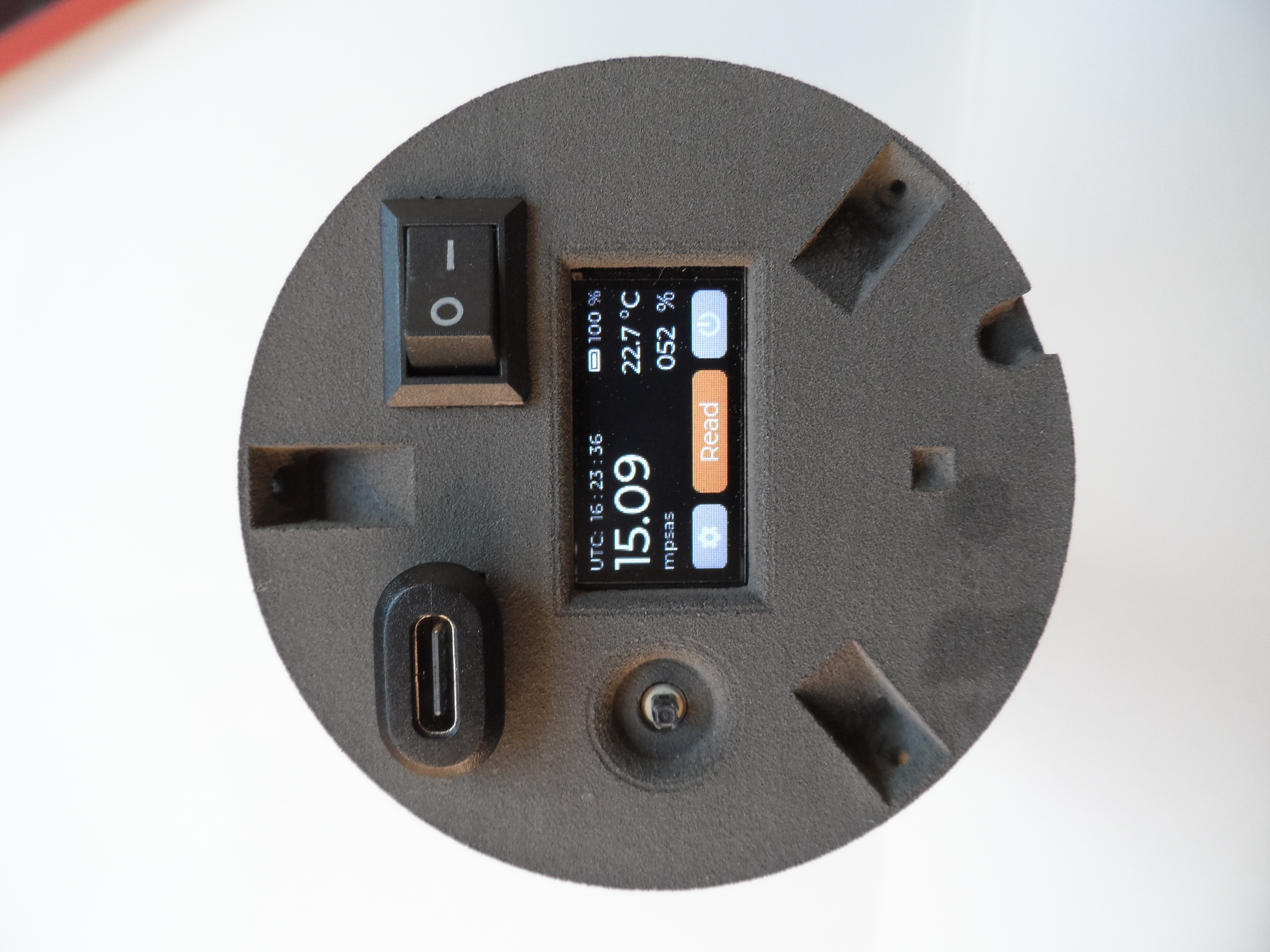
Front complete (display, switch and USB-C port) |
 |
Top support for TSL2591 with screws and wires |
 |
Top support fitted in the upper part |
 |
(CORRECT) Front complete |
Last edited by  José Carlos Dafonte Vázquez